
Portable fluid storage tank design and system

Active Publication Date: 2018-08-28
OMNI ENERGEY SERVICES CORP
View PDF28 Cites 0 Cited by
  • Summary
  • Abstract
  • Description
  • Claims
  • Application Information

AI Technical Summary

Benefits of technology

The invention is a portable fluid storage tank that is safer for operators who need to climb on top of it. It also makes it safer for operators to transfer from one tank to the next when multiple tanks are used.

Problems solved by technology

Many industries and operations such as drilling and fracturing operations often require the use of large amounts of fluids.
For example, fracturing a gas well in a shale formation often requires a large volume of fracturing fluids.
Because the storage tanks are kept on the operation site, they are often exposed to the elements such as rain, ice, and snow, as well as to the fluids stored in the tanks themselves.
This exposure has the propensity to make the tanks slick or slippery, thus adding additional risk of injury to the workers who may slip and fall from the large tanks while walking on top of a tank or moving from one tank to the next.
The prior art does not address the dangers posed to the operator as he transcends the top of the tank itself.

Method used


Image

  • Portable fluid storage tank design and system

Examples


Embodiment Construction

[0013]The subject matter of the present invention is described with specificity herein to meet statutory requirements. The terms and expressions which have been employed herein are used as terms of description and not of limitation, and there is no intention, in the use of such terms and expressions, of excluding any equivalents of the features shown and described or portions thereof, but it is recognized that various modifications are possible within the scope of the invention claimed. Rather, the claimed subject matter might be embodied in other ways to include different features or combinations of features similar to the ones described in this document, in conjunction with other present or future technologies.

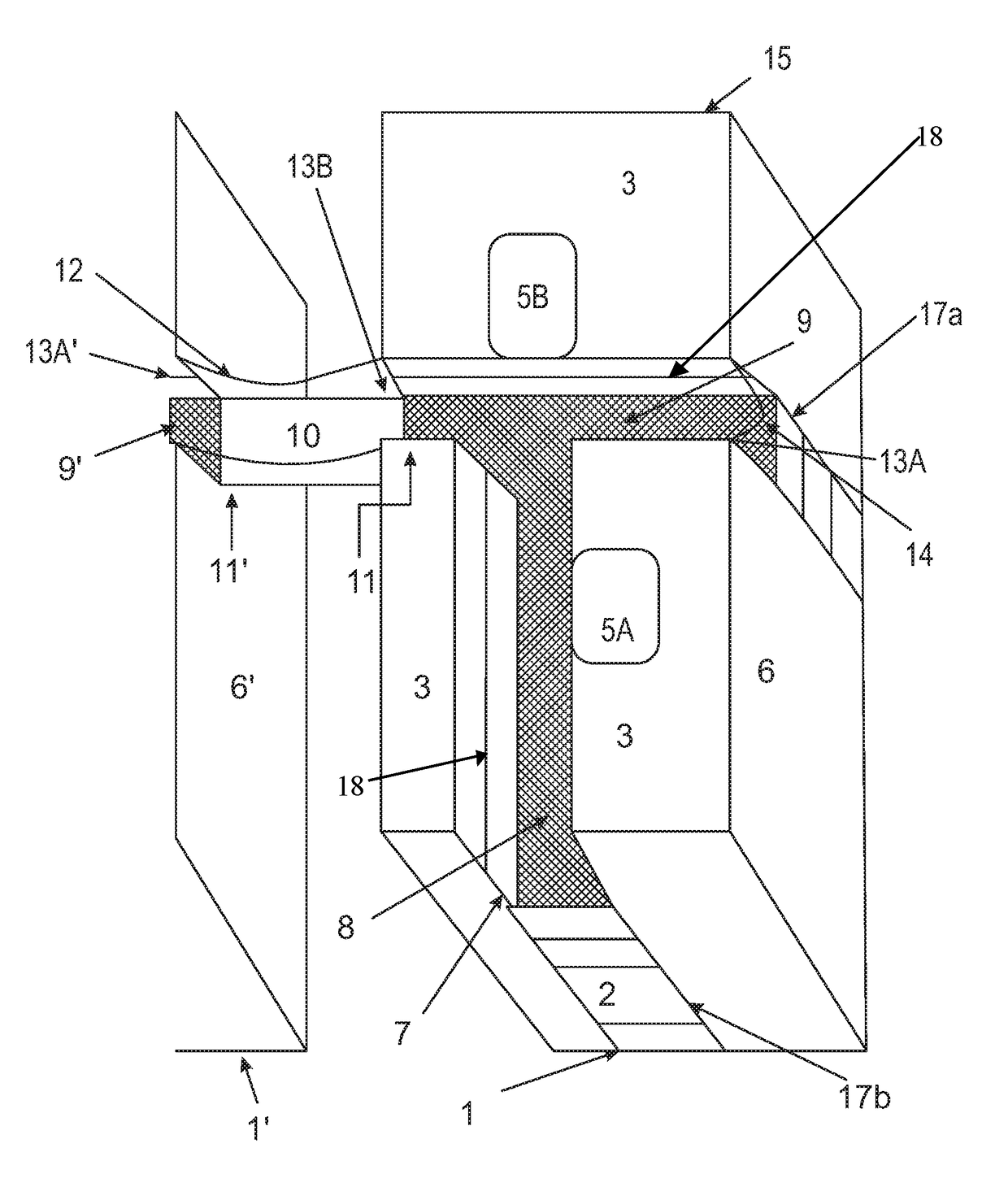
[0014]Referring to FIG. 1 of the drawings, an embodiment of the improved portable fluid storage tank design is shown as a frac tank wherein one said frac tank is shown juxtaposed to the cross section of a second frac tank. As embodied in FIG. 1, the frac tank comprises gener...


PUM


Abstract

An improved portable fluid storage tank comprising an enclosure having a bottom wall upon which the tank rests, a front or forward end, a back or rear end, a pair of opposed, vertically extending side walls, a top wall, and at least one recessed channel formed in said top wall whereby a walkway is formed to allow an operator to safely maneuver on top of said tank. In a further embodiment, a system of portable storage tanks is described wherein the walkways of two or more said improved portable storage tanks are connected thereby creating a walkway network between said improved portable fluid storage tanks.

Description

CROSS REFERENCE TO RELATED APPLICATIONS[0001]This application claims priority to U.S. Provisional Application No. 61 / 980,839, which was filed on Apr. 17, 2014.STATEMENT REGARDING FEDERALLY SPONSORED RESEARCH OR DEVELOPMENT[0002]Not Applicable.REFERENCE TO A “SEQUENCE LISTING,” A TABLE, OR A COMPUTER PROGRAM[0003]Not Applicable.BACKGROUND OF THE INVENTION[0004]Many industries and operations such as drilling and fracturing operations often require the use of large amounts of fluids. For example, fracturing a gas well in a shale formation often requires a large volume of fracturing fluids. Given the great deal of expense in the fracturing process, industry practice is to accumulate a large volume of fracturing fluids at the well site prior to commencing the fracturing process, thereby allowing for a continuous procedure. To accumulate the requisite volume of fracturing fluids, portable fluid storage tanks are used. The use of these tanks, sometimes referred to as frac tanks or mobile o...

Claims


Application Information

Patent Timeline
IPC IPC(8): E04G1/15E21B41/00E04G5/14
CPCE04G1/15E21B41/00E04G5/14B65D90/00B65D90/02B65D88/00
Inventor SHAW, LAWRENCE J.
Owner OMNI ENERGEY SERVICES CORP
Learn More