
Multi-chamber blowoff valve

a multi-chamber, blow-off valve technology, applied in valve housings, combustion air/fuel air treatment, machines/engines, etc., can solve problems such as excessive abundance of air in duct systems of vehicles, sudden decrease in speed, and difficulty in reducing speed, so as to achieve small volume and cross-sectional area

Inactive Publication Date: 2017-11-16
ACCESSIBLE TECHONOLOGIES
View PDF4 Cites 7 Cited by
  • Summary
  • Abstract
  • Description
  • Claims
  • Application Information

AI Technical Summary

Benefits of technology

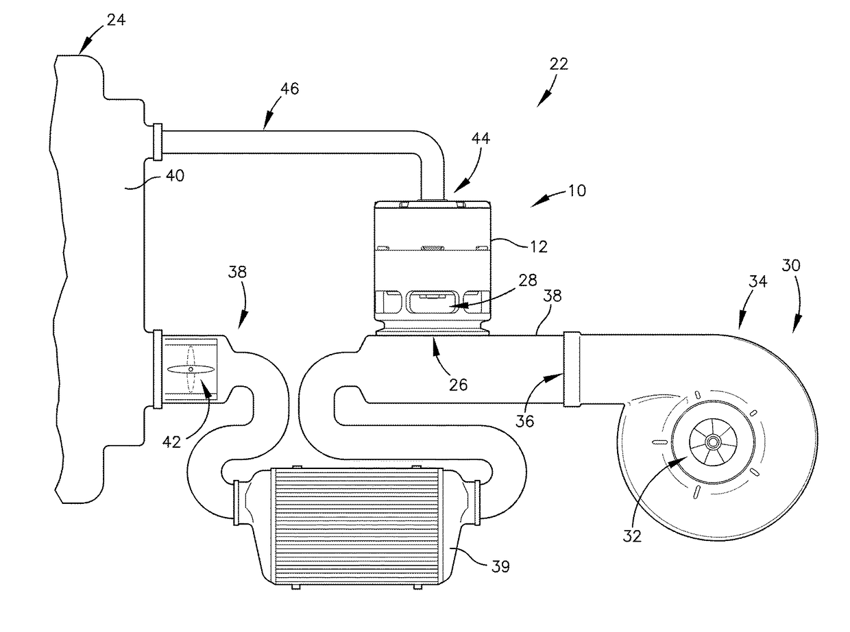
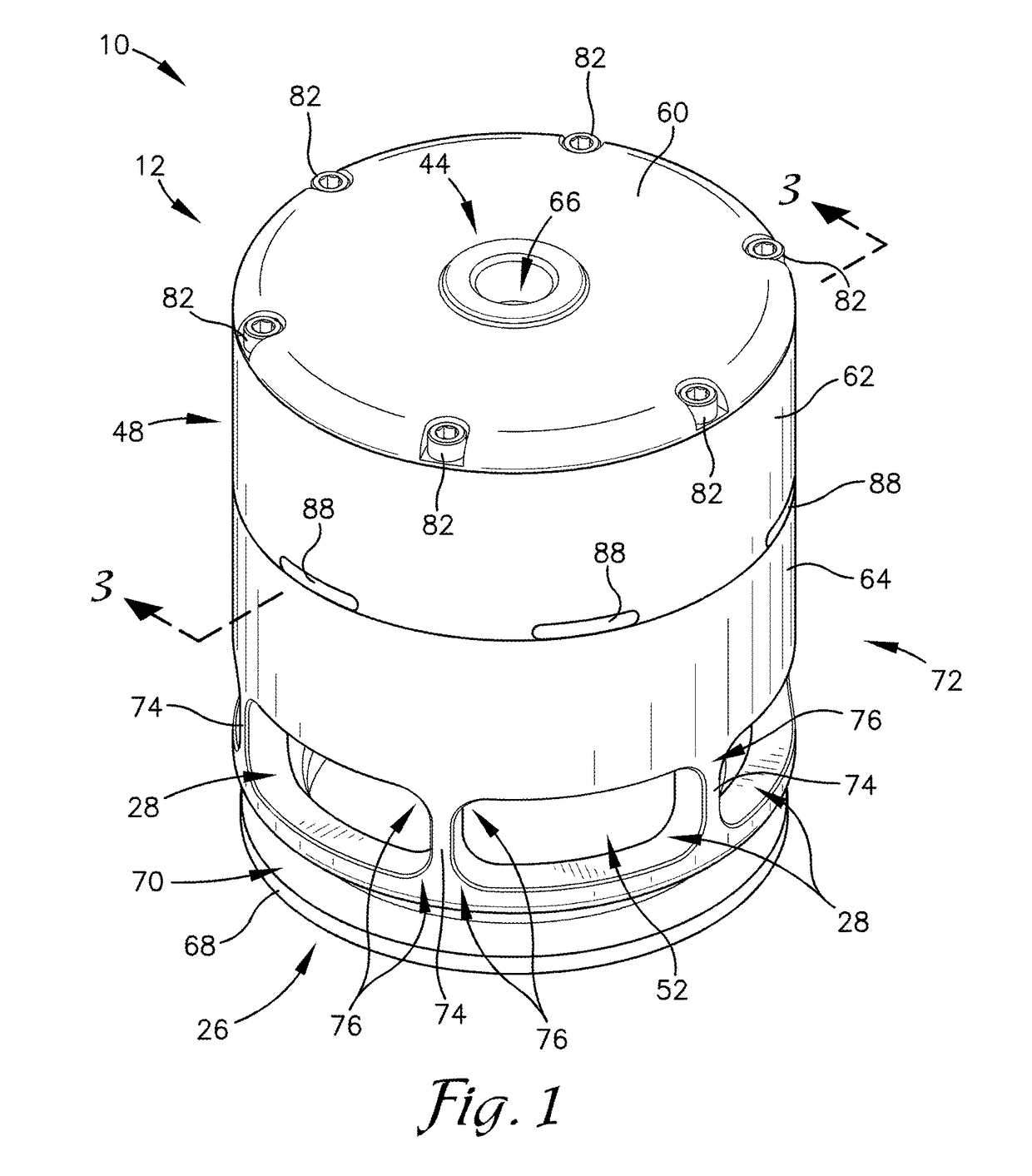
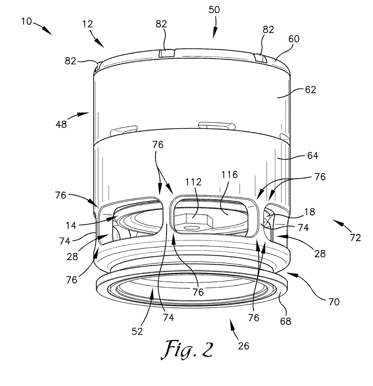
The invention provides a multi-chamber blowoff valve that solves problems by releasing excess air from a duct system of a vehicle. It is smaller in size and requires half the pressure / vacuum to actuate, resulting in minimal forces on the valve. The valve has multiple chambers that increase the surface area on which the manifold pressure has to exert force, allowing for more force to hold the valve shut when there is a high pressure differential from the ducting to the manifold. The multi-chamber blowoff valve may have two, three, or more chambers.

Problems solved by technology

However, sudden decreases in speed and power (such as by the driver removing their foot from the accelerator, thus closing the throttle) can be problematic to superchargers of the prior art.
Because there is a slight delay in compression of air by the supercharger following a reduction in speed and power, there is often an excessive abundance of air in a duct system of the vehicle when the throttle of the engine is closed.
This abundance of air in the duct system can be problematic for a few reasons.
First, the excessive air pressure can cause damage to engine components such as the throttle.
Second, the excessive air pressure can cause the air to travel back to the supercharger and damage supercharger components.
Often, the available space within an engine compartment is limited.
Further, larger superchargers require a larger blowoff valve to handle increased airflow and increased pressure differentials created by the increased airflow.
This saves vital space within a vehicle engine compartment.

Method used


Image

  • Multi-chamber blowoff valve
  • Multi-chamber blowoff valve
  • Multi-chamber blowoff valve

Examples


Embodiment Construction

[0023]The following detailed description references the accompanying drawings that illustrate specific embodiments in which the invention can be practiced. The embodiments are intended to describe aspects of the invention in sufficient detail to enable those skilled in the art to practice the invention. Other embodiments can be utilized and changes can be made without departing from the scope of the invention. The following detailed description is, therefore, not to be taken in a limiting sense. The scope of the invention is defined only by the appended claims, along with the full scope of equivalents to which such claims are entitled.

[0024]In this description, references to “one embodiment,”“an embodiment,” or “embodiments” mean that the feature or features being referred to are included in at least one embodiment of the technology. Separate references to “one embodiment,”“an embodiment,” or “embodiments” in this description do not necessarily refer to the same embodiment and are a...


PUM


Abstract

A multi-chamber blowoff valve is provided for releasing excess air pressure from a duct system associated with a vehicle. The blowoff valve has a valve housing, an engine-air interface, and a multiple piston assembly. The valve housing is configured to secure to the duct system at a duct-air interface. The engine-air interface is configured to allow air in and out of the valve housing. The multiple piston assembly is disposed within the valve housing and includes an upper piston and a lower piston that move in unison. The multiple piston assembly is configured to be in a closed position while a pressure differential is above a certain threshold and to be in an open position while the pressure differential is below said certain threshold. While in the open position, a portion of the air in the duct system is released.

Description

BACKGROUND1. Field[0001]Embodiments of the invention relate to blowoff valves for releasing excess air pressure. More specifically, embodiments of the invention relate to a multi-chamber blowoff valve configured to be used with a supercharger in a vehicle.2. Related Art[0002]Superchargers, turbochargers, and the like provide additional air to internal combustion engines. The additional air increases the power and work performed by the internal combustion engine by increasing the amount of fuel that can be burned at a given time. In essence, the supercharger acts as an air compressor to force air into the engine. Often, the air will travel from an outlet of the supercharger to an engine-air interface (typically a throttle) for the engine via a tubing, a piping, a direct connection, or the like.[0003]When the internal combustion engine is spinning rapidly, the supercharger in turn also spins rapidly. This mutual relationship is beneficial because the supercharger is feeding the additi...

Claims


Application Information

Patent Timeline
IPC IPC(8): F02M35/10F16K27/02F16K17/08F16K15/02F02M35/104F16K31/122F02B39/16
CPCF02M35/10255F02B39/16F02M35/104F02M35/10144F02M35/10157F16K15/026F16K17/08F16K27/0209F16K31/1225F16K17/082Y02T10/12Y10T137/2605Y10T137/2642
Inventor VAN LANT, TYLERCARLSON, MICHAEL A.
Owner ACCESSIBLE TECHONOLOGIES
Learn More