
Linear compressor

a compressor and linear technology, applied in the direction of positive displacement liquid engine, pump components, piston pump, etc., can solve the problems of deteriorating compressor performance, filter device not stably supported between the frame, compressor performance may deteriorate,

Active Publication Date: 2017-11-09
LG ELECTRONICS INC
View PDF2 Cites 4 Cited by
  • Summary
  • Abstract
  • Description
  • Claims
  • Application Information

AI Technical Summary

Benefits of technology

The patent text describes a linear compressor used in refrigerators and the need to increase the inner storage space of the refrigerator while maintaining the performance of the compressor. To reduce the size of the compressor, the size of the main part or component of the compressor needs to be reduced. However, reducing the size of the main part may result in a decrease in performance due to a reduced size of the gas bearing. To compensate for this, the compressor drive frequency may need to be increased, but this may increase friction force due to oil circulating in the compressor. To address these issues, the patent text proposes a gas bearing technology and a filter device for filtering refrigerant gas. The gas bearing technology uses a refrigerant gas supplied in a space between a cylinder and a piston to perform a bearing function. The filter device filters foreign substances from the refrigerant gas to prevent clogging of the nozzle of the cylinder. The frame of the compressor includes a frame body, a frame flange, and a frame inclination part, which allows for easy dispersion of stress and prevents deformation of the frame. The cylinder may have two gas inflow parts, and the gas hole of the frame may be disposed adjacent to the first gas inflow part to enhance the function of the gas bearing and prevent abrasion between the cylinder and piston. Overall, the patent text proposes a solution to improve the performance and stability of the linear compressor in refrigerators.

Problems solved by technology

Thus, the linear compressor having, a structure disclosed in the Prior Art Document 1 not adequate for the refrigerator for increasing the inner storage space thereof.
In this case, performance of the compressor may deteriorate.
However, the more the drive frequency of the compressor is increased, the more a friction force due to oil circulating into the compressor increases, deteriorating performance of the compressor.
According to such a constitution of the related art, the filter device is not stably supported between the frame and the cylinder, and an undesired movement occurs die to a flow of a high-pressure refrigerant gas.
As a result, the filter device does not cover an overall passage of the refrigerant gas.
Due to this, the filtering performance of the filter device is deteriorated and foreign substances flow into the nozzle of the cylinder.

Method used


Image

  • Linear compressor
  • Linear compressor
  • Linear compressor

Examples


Embodiment Construction

[0031]Hereinafter, exemplary embodiments will be described with reference to the accompanying drawings. The embodiments may, however, be embodied in many different forms and should not be construed as being limited to the embodiments set forth herein; rather, that alternate embodiments included in other retrogressive inventions or falling within the spirit and scope of the present disclosure will fully convey the concept to those skilled in the art.

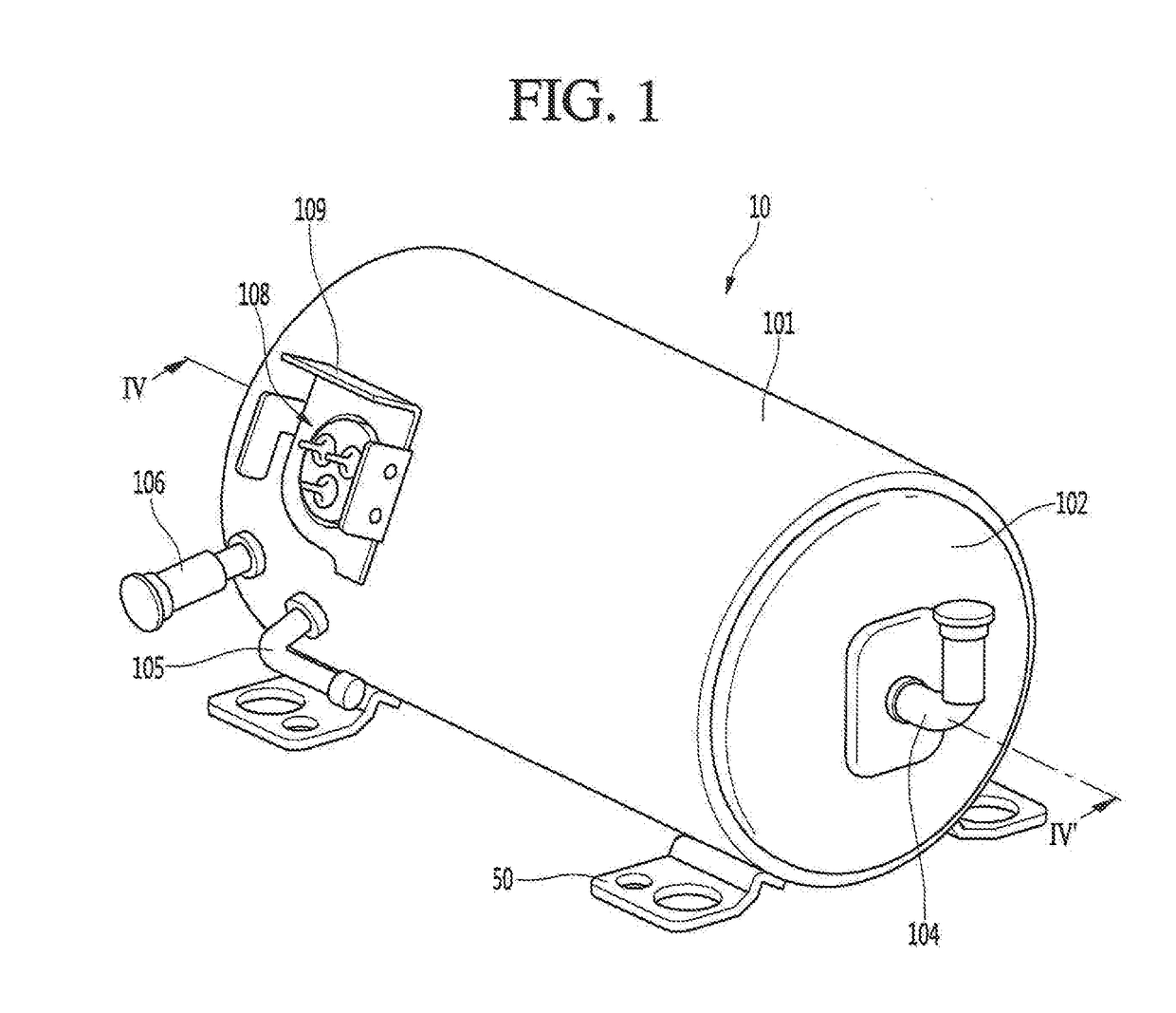
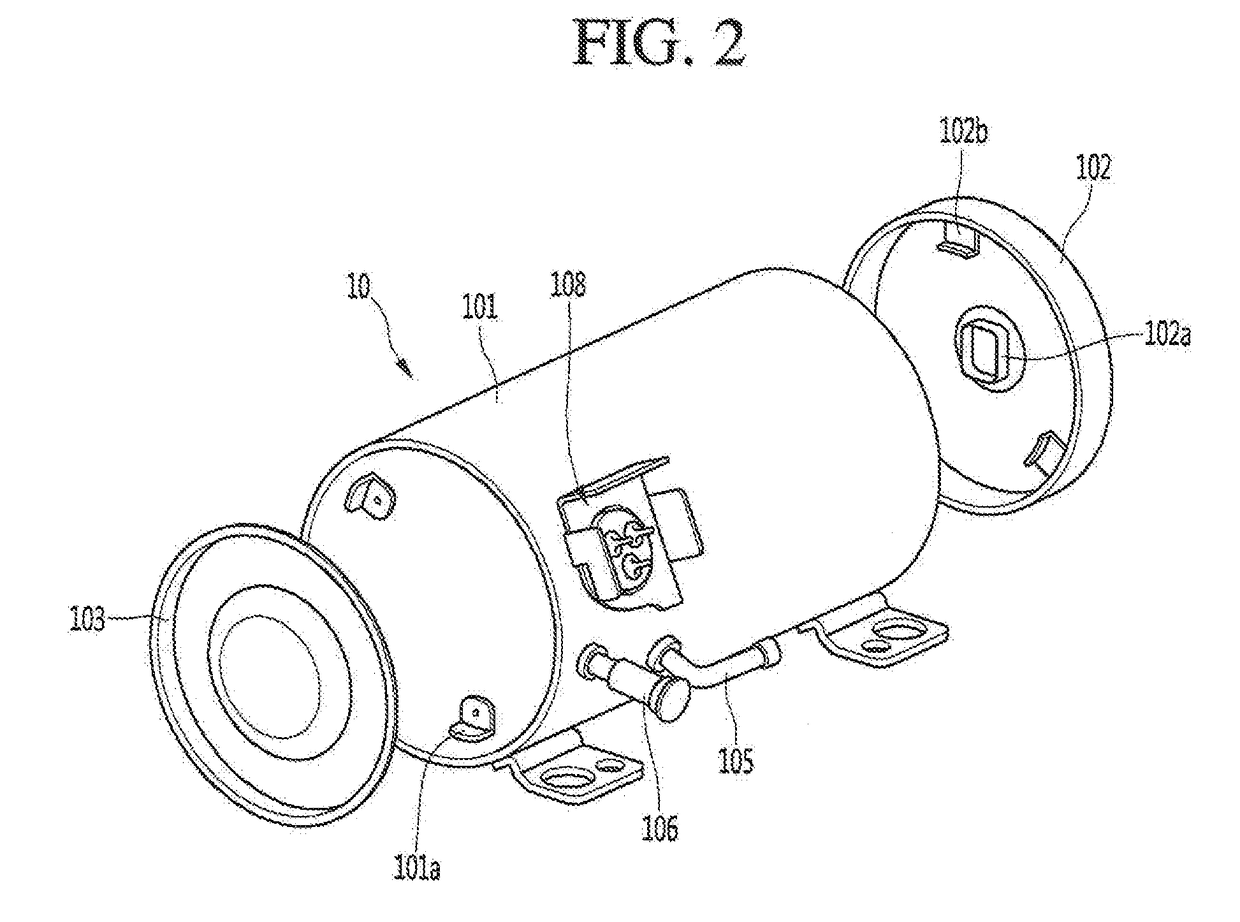
[0032]FIG. 1 is a perspective view illustrating an outer appearance of a linear compressor according to an embodiment. FIG. 2 is an exploded perspective view of a shell and a shell cover of the linear compressor according to an embodiment.

[0033]Referring to FIGS. 1 and 2, a linear compressor 10 according to an embodiment may include a shell 101 and shell covers 102 and 103 coupled to the shell 101. Each of the first and second shell cover 102 and 103 may be understood as one component of the shell 101.

[0034]A leg 50 may be coupled to a lo...


PUM


Abstract

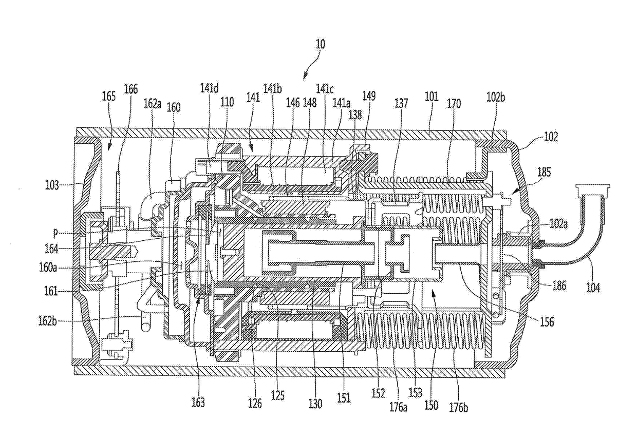
A linear compressor is provided. The linear compressor may include a frame coupled to a cylinder, a gas hole defined in the frame, and a gas pocket that communicates with the gas hole and transfers a refrigerant gas to the cylinder.

Description

CROSS-REFERENCE TO RELATED APPLICATION(S)[0001]The present application claims priori under 35 U.S.C. 119 and 35 U.S.C. 365 to Korean Patent Application No. 10-2016-0054892, filed in Korea on May 3, 2016, which is hereby incorporated by reference in its entirety.BACKGROUNDField[0002]A linear compressor is disclosed herein.Background[0003]Cooling systems are systems in which a refrigerant circulates to generate cool air. In such a cooling system, processes of compressing, condensing, expanding, and evaporating the refrigerant are repeatedly performed. For this, the cooling system includes a compressor, a condenser, an expansion device, and an evaporator. Also, the cooling system ray be installed in a refrigerator or air conditioner which is a home appliance.[0004]In general, compressors are machines that receive power from a power generation device, such as an electric motor or a turbine, to compress air, a refrigerant, or various working gases, thereby increasing pressure. Compressor...

Claims


Application Information

Patent Timeline
Patent Type & Authority Applications(United States)
IPC IPC(8): F04B35/04F04B17/04
CPCF04B35/045F04B17/04F04B39/0005F04B39/121F04B39/16F04B39/04F04B39/10F04B39/122F04B53/20F04B39/023F04B39/0292F04B39/123
Inventor LEE, KYEONGWEONKIM, CHANGKYUPARK, JOONSUNGJUNG, WONHYUNHAN, YOUNGCHEOL
Owner LG ELECTRONICS INC
Learn More