
Beam connector for arch structure

a technology for connecting beams and arch structures, applied in the direction of roofs, constructions, roofs, etc., can solve the problems of increasing costs, unstable end-to-end alignment of beams, and difficulty in double row or larger polygonal arches, so as to add convenience during construction, or achieve structural durability

Active Publication Date: 2017-10-19
HILDESTAD ROY
View PDF1 Cites 10 Cited by
  • Summary
  • Abstract
  • Description
  • Claims
  • Application Information

AI Technical Summary

Benefits of technology

The patent text describes a connector that can easily hold beams in place without requiring fasteners. The top and bottom brackets can balance each other out, allowing for flexibility in construction. The top brackets can also be designed to fully enclose the ends of the beams, which makes it easier to use smaller elements like bamboo poles and small diameter timber. The technical effects of this invention include its ease of installation and versatility in beam selection.

Problems solved by technology

Current designs for double row or larger polygonal arches present difficulties when applied to structures with spans above 40 feet (12 m) that need to meet public load safety standards, or that need to be dismantled easily and reused, or which are constructed without scaffolding, assembled without heavy equipment, and built with bamboo or other locally-available beam materials, or which need to be safely and reliably assembled by non-professionals.
Although a polygonal arch makes good use of materials, the end-to-end alignment of the beams is unstable.
Adding enough bracing to make a single row of beams rigid increases costs and lowers the strength-to-weight ratio.
Some designs provide modularity, reusability and safety, but the benefits are limited primarily to one material, or to very small structures.
A single design which addresses the combined requirements of cantilevering, allowing a wide range of beam materials, and reducing construction time, which can be scaled up to build structures with spans of 20 meters or more, is lacking.

Method used


Image

  • Beam connector for arch structure
  • Beam connector for arch structure
  • Beam connector for arch structure

Examples


Embodiment Construction

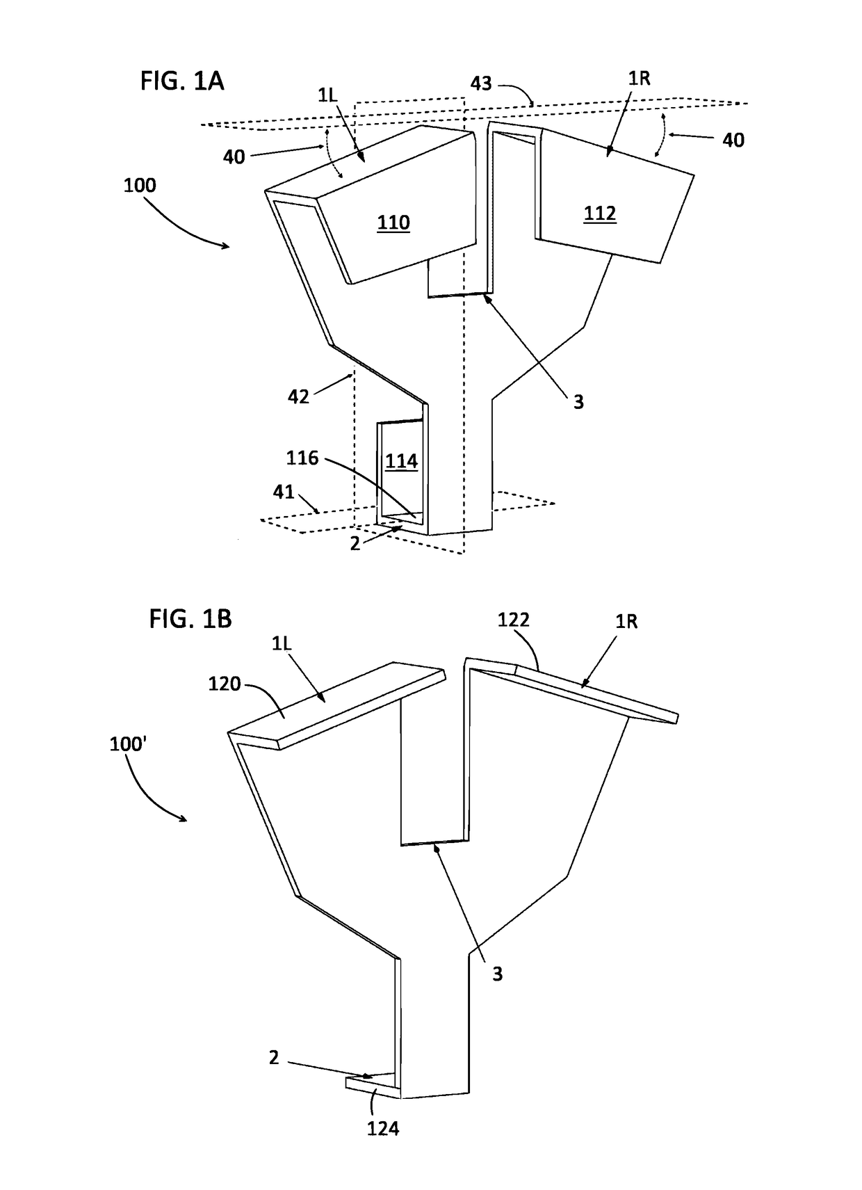
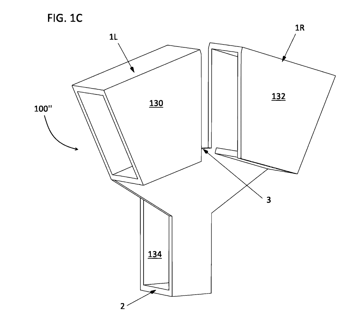
[0041]Referring to FIG. 1A, one embodiment of the invention is a Y-shaped structural connector 100 having three U-shaped brackets designed to bind three stringer beams to the union created by the connector. One U-shaped bracket is located on each arm of the KY′. Each of the brackets 110 and 112 form the upper arms 1L, 1R, respectively, of the ‘Y’ shaped connector 100. Each of these brackets 110, 112 binds the end of a stringer beam to the connector 100. The top brackets are aligned with each other so that they are mirror images of each other relative to the vertical, front-to-back midplane 42 of the connector 100. The U-shaped bracket 114 forms the bottom arm 2 of connector 100. Bracket 114 binds the midsection of a third stringer beam to the connector 100. The bottom bracket 114 is aligned with the top brackets 110 and 112 so that a beam fully inserted into either top bracket 110, 112 will slope toward the level of the bottom surface 116 of the bottom bracket 114. Both top brackets...


PUM


Abstract

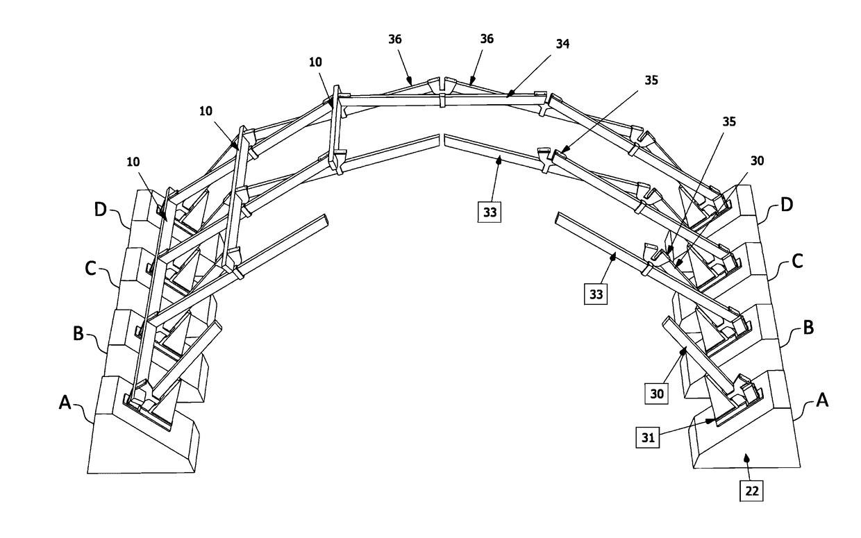
The invention is a structural connector used as a component to construct an arch consisting of a plurality of closely adjacent, polygonal rows of stringer beams. The multiple row polygonal arch is a low-cost, general purpose support structure for bridges, shelters and arbors applicable to many cost-, time- or environmentally-sensitive situations. The invention is a Y-shaped connector, typically made of sheet metal, with three brackets, two upper brackets and a lower bracket, which collectively enable a union of three beams forming one node of the multiple row polygonal arch. Using these Y-shaped connectors to join the beams at each node creates the arch structure, and additionally provides the features of cantilevering, modularity, generic component shape, reusability and safety. The invention is applicable to a variety of structures such as: pedestrian and vehicular bridges, shelters, arbors, as well as jewelry, furniture and toys.

Description

BACKGROUND OF INVENTION[0001]Current designs for double row or larger polygonal arches present difficulties when applied to structures with spans above 40 feet (12 m) that need to meet public load safety standards, or that need to be dismantled easily and reused, or which are constructed without scaffolding, assembled without heavy equipment, and built with bamboo or other locally-available beam materials, or which need to be safely and reliably assembled by non-professionals.[0002]What are needed are connectors that enable the construction of arch-shaped structures either individually or as parallel ribs of cylindrically-shaped structures such as supporting arches for bridges, tunnel linings, Quonset hut-type shelters and arbors. The need is for a connector that enables the construction of arches where the stringer beams are arranged in two or more parallel rows so that the ends of the beams in one row are opposite the midsection of the beams in an adjacent row. Arches constructed ...

Claims


Application Information

Patent Timeline
Patent Type & Authority Applications(United States)
IPC IPC(8): E04B1/32
CPCE04B1/3205E04B2001/3276E04B2001/3241E04B1/32E04B1/2608E04B7/06E04B2001/2415E04B2001/2463E04B2001/2616E04B2001/2644E04B2001/2684E04D12/008
Inventor HILDESTAD, ROY
Owner HILDESTAD ROY
Learn More