
Photographing Device for Vehicle

Active Publication Date: 2017-10-12
TOYOTA JIDOSHA KK
View PDF3 Cites 17 Cited by
  • Summary
  • Abstract
  • Description
  • Claims
  • Application Information

AI Technical Summary

Benefits of technology

The present patent aims to provide a photographing device for a vehicle that can reduce the probability of a heater (heating wire) staying at a high temperature for a long time, which can cause damage. The device includes a current limiting element that prevents excessive heating of the heater by reducing or eliminating the flow of current when a short circuit occurs. The current limiting element is placed in a position that allows it to easily heat up when a short circuit occurs, which helps to quickly lower the heater's temperature. This prevents the heater from staying at a high temperature for too long, which could cause damage. The device is designed to be cost-effective and to simplify the structure of the electric circuit. Its design also allows for efficient use of heat generated by the heater, ensuring that it is applied to the intended section of the device.

Problems solved by technology

Incidentally, using an air heating in the vehicle when an outdoor air temperature of the vehicle is low may generate dewing on the beam transmission section of the front window.
In addition, when the outdoor air temperature is low, ice or frost may adhere to the vehicle outer surface of the beam transmission section.
When such a phenomenon occurs in the beam transmission section, the imaging element may image an unclear subject image or may be unable to image an obstacle.
For this reason, in this case, the control device may be unable to perform determination of whether the imaged subject is an obstacle and calculation of the distance from the vehicle to the obstacle.
When power is continuously supplied to the heater (the heating wire) for a long time, the heater may be excessively heated to a high temperature and the high temperature state may continue for a long time.
As a result, since the imaging element is heated for a long time by radiant heat from the heated beam transmission section, the imaging element may be unable to exhibit desired performance.
That is, the imaging element may image an unclear subject image or may be unable to image the obstacle.
That is, power supply to the heater is controlled such that the excessively high temperature state of the heater does not maintain for a long time.
However, if a short circuit occurs in the electric circuit and the power from the power supply is directly supplied to the heater without going through the switch element, the heater continues heating for a long time.
As a result, the excessively high temperature state of the heater can maintain for a long time.
When the current flowing through the heater becomes zero, the heater cannot maintain an excessively high temperature state.
Similarly, when the current flowing through the heater is reduced, the heater cannot maintain the excessively high temperature state.
However, because the section to be heated cannot be evenly heated as a whole, the center of gravity is most easily heated, and the temperature is easily lowered from the center of gravity toward a circumferential edge portion.
For this reason, if the current limiting element is disposed on a straight line passing through the circumferential edge portion of the section to be heated and extending in a plate thickness direction of the section to be heated, for example, the current limiting element is not easily heated to a high temperature when a short circuit occurs in the electric circuit.
However, when the present disclosure is configured in this way, for example, the current limiting element is easily heated to a high temperature when a short circuit occurs in the electric circuit.

Method used


Image

  • Photographing Device for Vehicle
  • Photographing Device for Vehicle
  • Photographing Device for Vehicle

Examples


Embodiment Construction

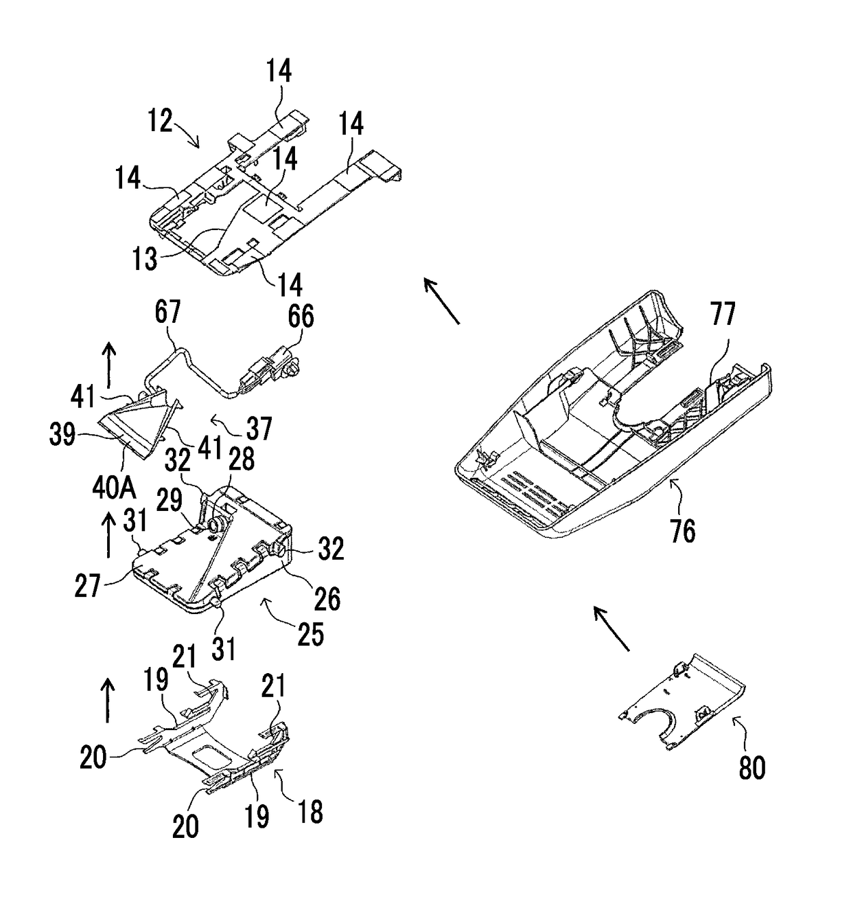
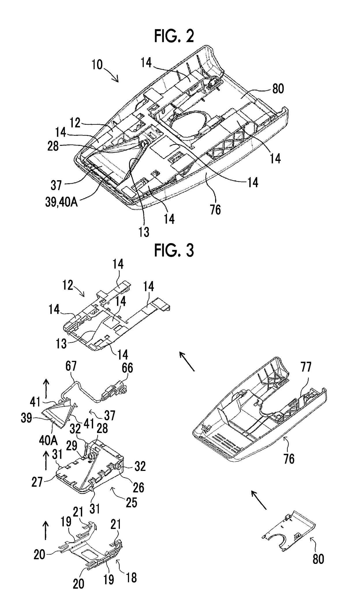
[0045]Hereinafter, a photographing device for a vehicle according to an embodiment of the present disclosure will be described with reference to the accompanying drawings.

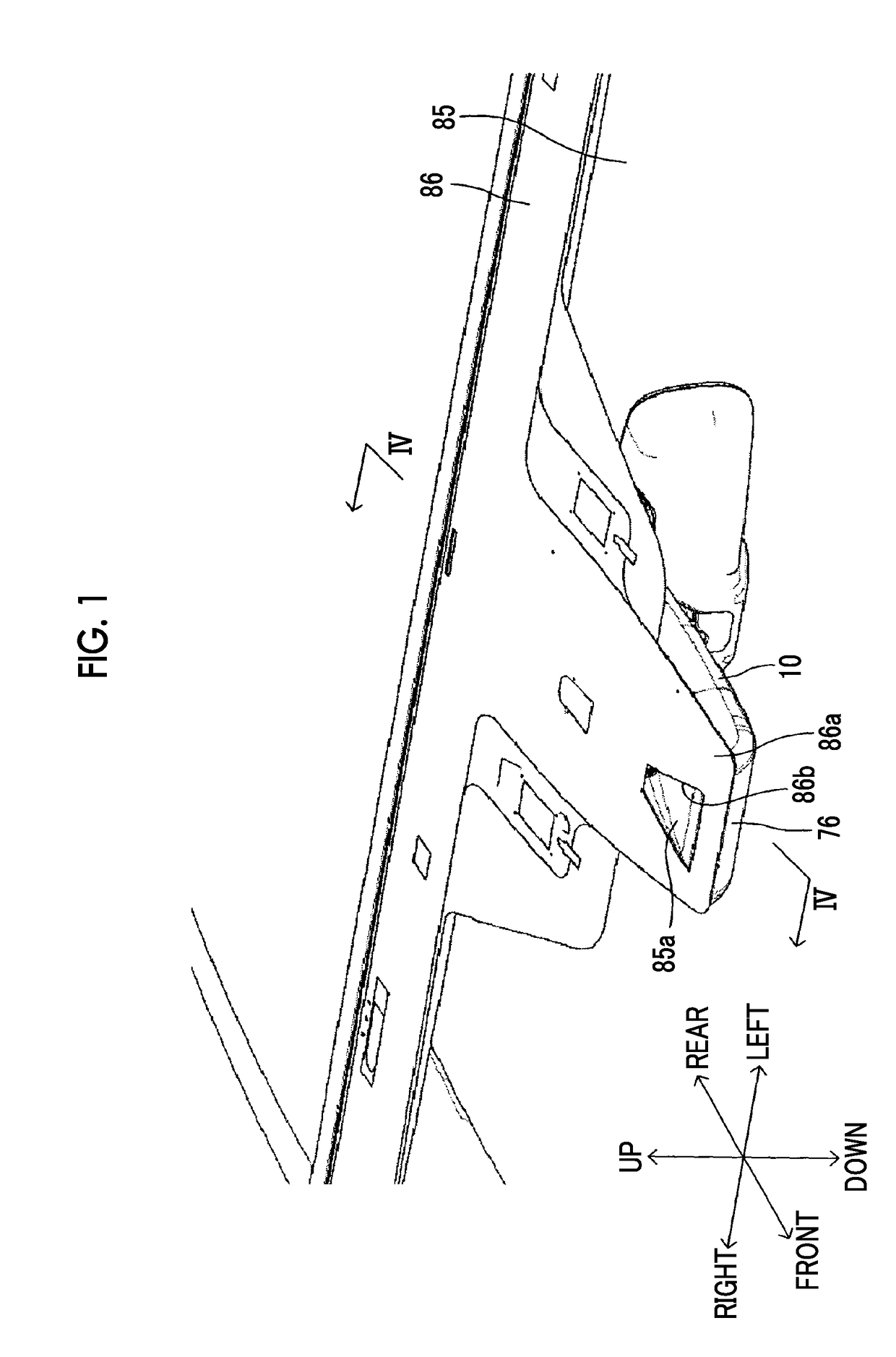
[0046]A vehicle includes a front window 85 shown in FIG. 1 and FIG. 4. The front window 85 is formed of a transparent material (for example, glass, a resin, or the like). As shown in FIG. 1 and FIG. 4, the front window 85 is inclined with respect to a vehicle body in a state in which the front window 85 is gradually directed forward from top to bottom.

[0047]As shown in FIG. 1, a shading sheet 86 formed in substantially a T shape as a whole is attached to an upper edge portion of a rear surface (i.e., the surface inside the vehicle) of the front window 85 and the vicinity thereof. A forward extension section 86a extending obliquely forward and downward is formed at a central portion of the shading sheet 86. A light transmission hole 86b having a substantially trapezoidal shape is formed in the vicinity of the front ...


PUM


Abstract

A photographing device for a vehicle includes: an imaging element configured to receive a photographing beam passing through a beam transmission section of a window section; a heater constituted by a heating wire; a section to be heated to which the heater is fixed, the section to be heated being opposite to an inner side surface of the beam transmission section; a switch element configured to switch electrical connection state to the heater; and a current limiting element disposed at the section to be heated and being configured such that current flowing through the heater becomes zero or is reduced when the electric circuit is short-circuited such that power is supplied to the heater while bypassing the switch element and a temperature of the current limiting element become equal to or higher than a predetermined value.

Description

INCORPORATION BY REFERENCE[0001]The disclosure of Japanese Patent Application No. 2016-076275 filed on Apr. 6, 2016 including the specification, drawings and abstract is incorporated herein by reference in its entirety.BACKGROUND1. Technical Field[0002]The present disclosure relates to a photographing device for a vehicle.2. Description of Related Art[0003]A photographing device may be installed on a front window of a vehicle on the surface inside the vehicle. For example, such a photographing device is used as a portion of a pre-crash safety system (hereinafter referred to as “PCS”).[0004]This type of a photographing device includes a bracket fixed to the inner surface (the rear surface) of the front window, and a camera unit supported by the bracket. The camera unit includes a lens and an imaging element disposed immediately behind the lens.[0005]For example, when another vehicle (hereinafter referred to as “a forward vehicle”) is disposed in front of the vehicle on which the PCS ...

Claims


Application Information

Patent Timeline
IPC IPC(8): H05B3/06G02B27/00H05B3/20H04N7/18B60R11/04
CPCH05B3/06H04N7/183B60R11/04H05B3/20H05B2203/003G06K9/00805B60R2011/0026B60R2011/0063G02B27/0006B60S1/60H05B3/86B60S1/0848H05B1/0236H05B3/84H05B2203/013B60S1/026B60R21/0134B60S1/56H04N23/00G06V20/58
Inventor USAMI, MASAYUKITOYOFUKU, KUNIHIKOSHINKAI, RYUICHI
Owner TOYOTA JIDOSHA KK
Learn More