Eureka AIR delivers breakthrough ideas for toughest innovation challenges, trusted by R&D personnel around the world.

Wide angle joint

a wide angle joint and angle technology, applied in the direction of couplings, mechanical devices, transportation and packaging, etc., can solve the problems of increased wear of the plate and the coupling yoke, vibration and noise between the plate and the yoke coupling, etc., to reduce vibration and noise, reduce wear, and reduce the effect of shock

Active Publication Date: 2017-10-12
HL MANDO CORP
View PDF6 Cites 2 Cited by
  • Summary
  • Abstract
  • Description
  • Claims
  • Application Information

AI Technical Summary

Benefits of technology

The present invention provides a wide angle joint for a vehicle that can minimize a shock caused by a reverse input from a road and can reduce vibration and noise while decreasing wear.

Problems solved by technology

The above-configured wide angle joint in the related art has a problem in that wear of the plate and the coupling yoke is intensified on account of a shock caused by a reverse input from a road.
Further, the wide angle joint has a problem in that excessive wear of the plate may cause vibration and noise between the plate and the yoke coupling.

Method used


Image

  • Wide angle joint
  • Wide angle joint
  • Wide angle joint

Examples


Embodiment Construction

[0022]Hereinafter, embodiments of the present invention will be described in detail with reference to the accompanying drawings. In adding reference numerals to elements in each drawing, the same elements will be designated by the same reference numerals, if possible, although they are shown in different drawings. Further, in the following description of the present invention, a detailed description of known functions and configurations incorporated herein will be omitted when it is determined that the description may make the subject matter of the present invention rather unclear.

[0023]In addition, terms, such as first, second, A, B, (a), (b) or the like may be used herein when describing components of the present invention. These terms are merely used to distinguish one structural element from other structural elements, and a property, an order, a sequence and the like of a corresponding structural element are not limited by the term. It should be noted that if it is described in ...


PUM


Abstract

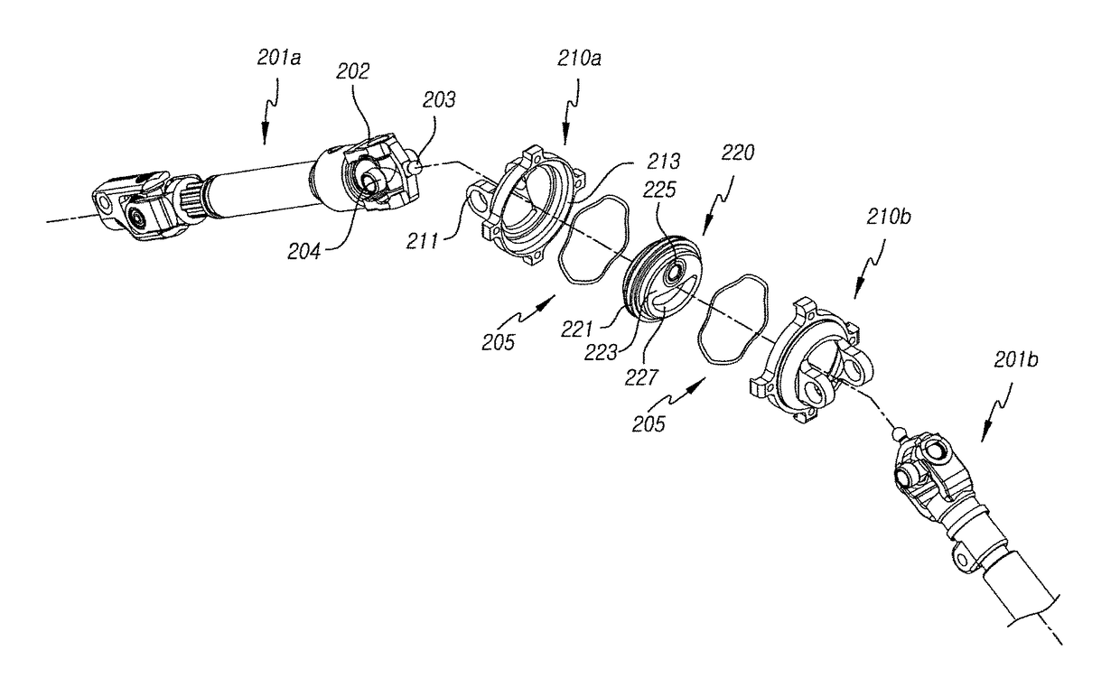
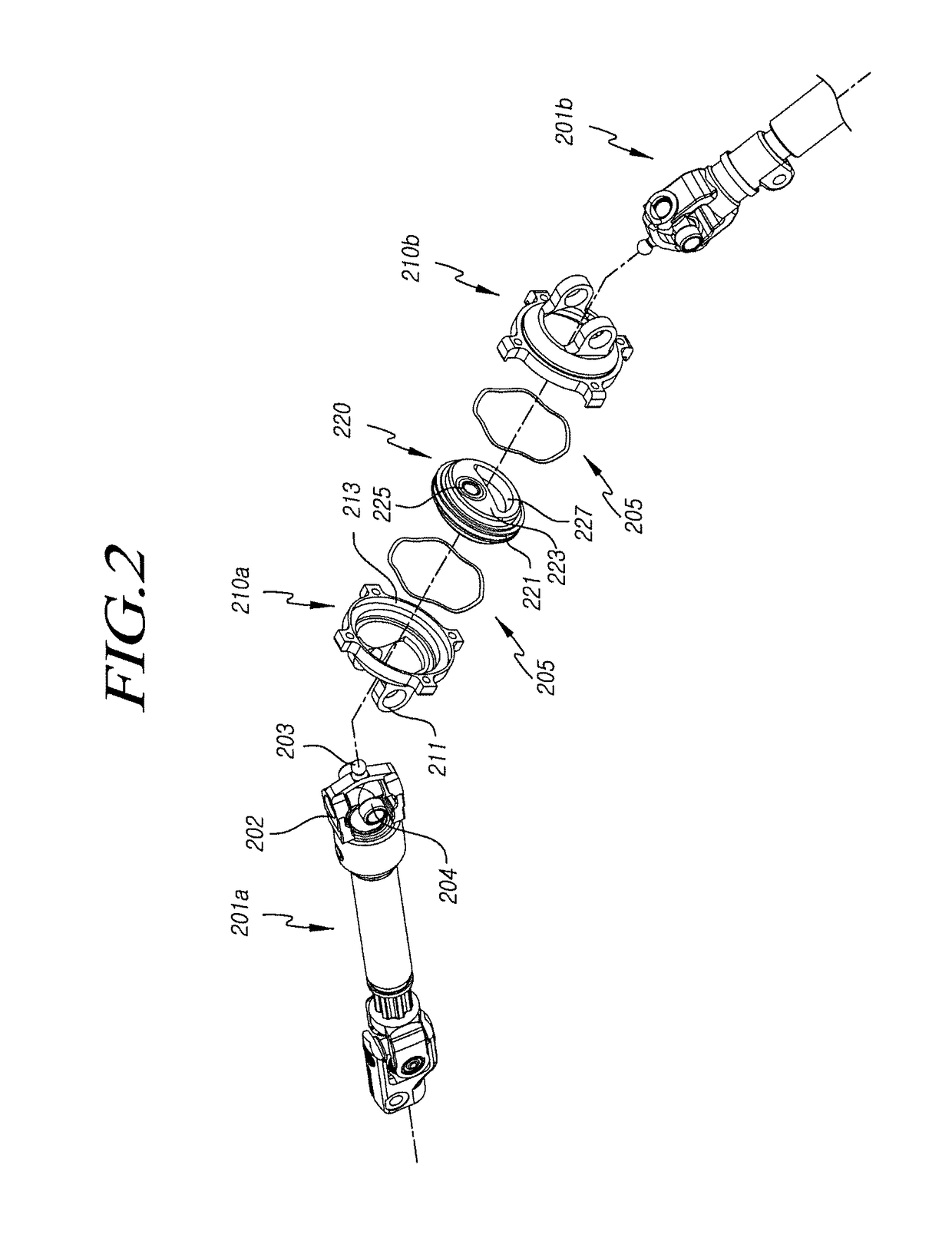
The present invention provides a wide angle joint including: a pair of yoke shafts mounted on opposite sides thereof to transmit power from the one side to the opposite side, each yoke shaft having a ball end portion provided on a first yoke part to which a spider is coupled; a plate having a large-diameter part formed in the middle thereof and protruding parts protruding from the large-diameter part in the opposite axial directions while being reduced in a radially inward direction, wherein the protruding parts have insertion recesses into which the ball end portions of the yoke shafts are inserted, and the large-diameter part is faulted to have different widths in radial directions from the central portion thereof; and a pair of coupling yokes, each of which has a second yoke part connected with the first yoke part through the spider and a support recess into which the large-diameter part of the plate is inserted.

Description

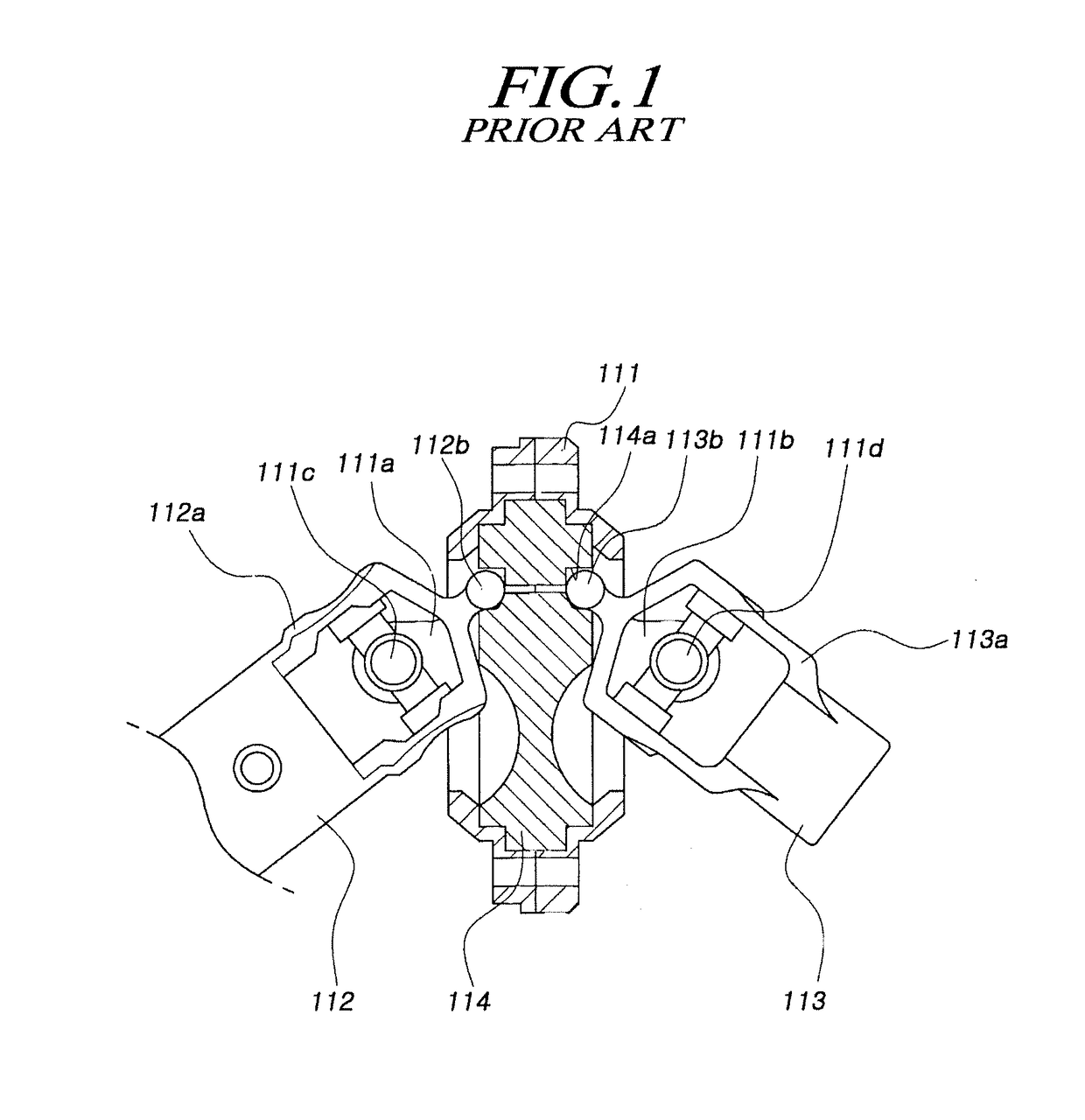
CROSS REFERENCE TO RELATED APPLICATION[0001]This application claims priority from Korean Patent Application No. 10-2016-0042204, filed on Apr. 6, 2016, which is hereby incorporated by reference for all purposes as if fully set forth herein.BACKGROUND OF THE INVENTION1. Field of the Invention[0002]The present invention relates to a wide angle joint, and more specifically, to a wide angle joint for a vehicle that can minimize a shock caused by a reverse input and can reduce vibration and noise while decreasing wear.2. Description of the Prior Art[0003]In general, a universal joint is bent to about 35 degrees or less to transmit power, whereas a wide angle joint is bent to an angle ranging from about 60 degrees to about 70 degrees to transmit power.[0004]The wide angle joint has a plate assembly installed inside a pair of coupling yokes and yoke shafts connected to opposite sides of an eccentric position on the plate assembly.[0005]FIG. 1 is a sectional view schematically illustrating ...

Claims


Application Information

Patent Timeline
Patent Type & Authority Applications(United States)
IPC IPC(8): F16D3/26B60G7/00F16D3/22
CPCF16D3/26F16D3/22F16C11/06B60G2204/416F16C2326/05B60G7/005F16C11/0623F16D2300/22F16C2361/41F16D3/32F16D3/16
Inventor PARK, SUNG HUNMOON, SUNGJUNE
Owner HL MANDO CORP
Why Eureka
Eureka Blog
Learn More