Projector and method for controlling projector

Active Publication Date: 2017-10-05
SEIKO EPSON CORP
View PDF5 Cites 3 Cited by
  • Summary
  • Abstract
  • Description
  • Claims
  • Application Information

AI Technical Summary

Benefits of technology

The invention is about a projector and a way to control it that allows for quick lens changes while also reducing power consumption.

Problems solved by technology

When the projector transitions to a power supply mode in which power consumption is lowered, the projection lens cannot be moved in some cases, and in a case where the projection lens is not located in an attachment / detachment position where the projection lens can be attached and detached, the projection lens cannot be detached.

Method used


Image

  • Projector and method for controlling projector
  • Projector and method for controlling projector
  • Projector and method for controlling projector

Examples


Embodiment Construction

[0030]An embodiment of the invention will be described below with reference to the drawings.

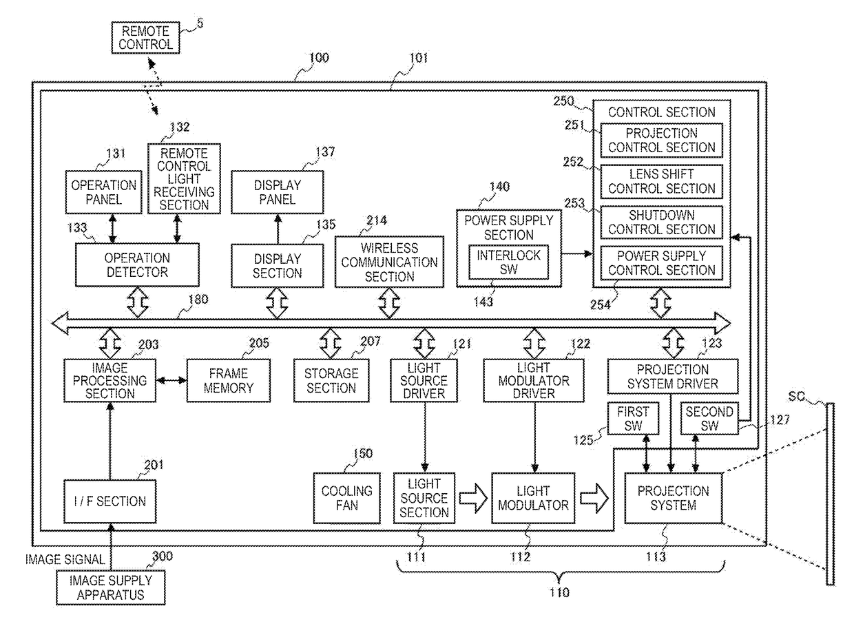
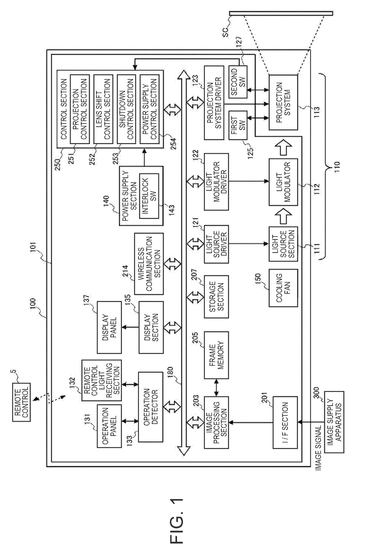
[0031]FIG. 1 is a functional block diagram showing the configuration of a projector 100.

[0032]The projector 100 is connected to an external image supply apparatus 300, such as a personal computer and a variety of video players, and projects an image based on an image signal supplied from the image supply apparatus 300 on a projection target.

[0033]Examples of the image supply apparatus 300 may include a video reproduction apparatus, a DVD (digital versatile disk) reproduction apparatus, a television tuner, a CATV (cable television) set-top box, a video output apparatus, such as a video game console, and a personal computer. The projection target may be an object that is not uniformly flat, such as an exterior wall of a building, or may be an object that is uniformly flat, such as a screen SC. FIG. 1 shows a case where the projection target is the screen SC by way of example.

[0034]The projector...


PUM


Abstract

A projector including a light source, a power supply section, a power supply control section that controls power supply from the power supply section, a projection lens that projects an image, and a projection system driver that moves the projection lens, wherein the power supply control section performs, as power supply modes, an operation mode in which power is supplied to the light source section to allow the light source section to output light and a first standby mode in which the power supply to the light source section is terminated, and in the first standby mode, power is supplied to the projection system driver to allow the projection lens to move to an attachment / detachment position where the projection lens is attachable and detachable.

Description

CROSS-REFERENCE[0001]The entire disclosure of Japanese Patent Application No. 2016-070419, filed Mar. 31, 2016 is expressly incorporated by reference herein.BACKGROUND1. Technical Field[0002]The present invention relates to a projector and a method for controlling the projector.2. Related Art[0003]There has been a known projector of related art capable of changing a projection lens (see JP-A-2014-137513, for example).[0004]The projector described in JP-A-2014-137513 includes a lens change detector that detects operation of attaching and detaching a lens cover or a lens unit and a controller that determines whether the lens cover or the lens unit is attached or detached on the basis of a signal from the lens change detector. When the controller determines that the lens cover or the lens unit has been detached, the operation mode is switched from a projection mode to a lens change mode, and at least a light source is powered off.[0005]In order to lower power consumption, a projector h...

Claims


Application Information

Patent Timeline
IPC IPC(8): G03B21/14H04N9/31G03B21/20
CPCG03B21/142G03B21/006H04N9/315G03B21/2053G03B21/206H04N9/3141G02B7/14
Inventor FURIHATA, TAKESHIYANAGIHARA, DAISUKE
Owner SEIKO EPSON CORP
Why Eureka
Try Eureka