
Monitoring sites containing switchable optical devices and controllers

a technology of optical devices and controllers, applied in the field of monitoring sites, can solve the problems of increasing the sophistication of control and monitoring systems, and achieve the effects of increasing the switching voltage, enhancing the comfort of the occupant, and auto-correcting the degradation

Active Publication Date: 2017-10-05
VIEW INC
View PDF29 Cites 71 Cited by
  • Summary
  • Abstract
  • Description
  • Claims
  • Application Information

AI Technical Summary

Benefits of technology

The patent describes a system for monitoring multiple remote sites with switchable optical devices. The system analyzes data from the devices to identify any that are performing outside of their expected range. The system can then take corrective actions to bring the devices back into their expected range. The system can also learn from user preferences and adjust its control logic accordingly. The technical effects of the patent include improving the monitoring and control of switchable optical devices in remote sites, as well as providing application services and reports to users. The system can also adapt based on data from the remote sites to improve energy efficiency and occupant comfort.

Problems solved by technology

As such windows gain acceptance and are more widely deployed, they may require increasingly sophisticated control and monitoring systems, as there may be a large amount of data associated with smart windows.

Method used


Image

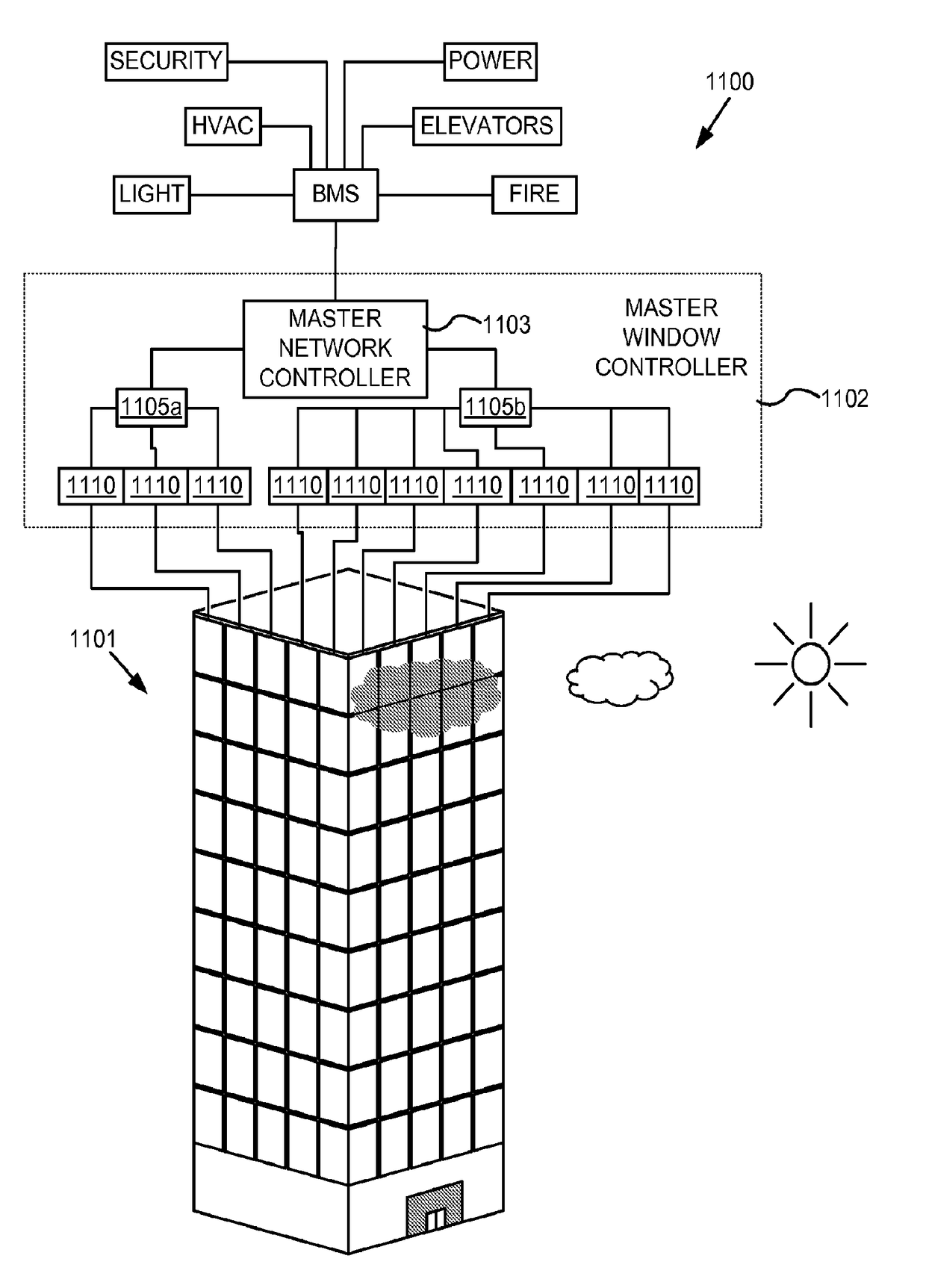
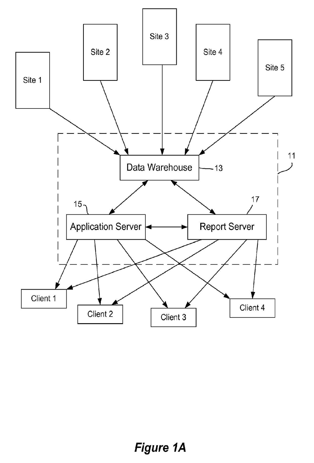
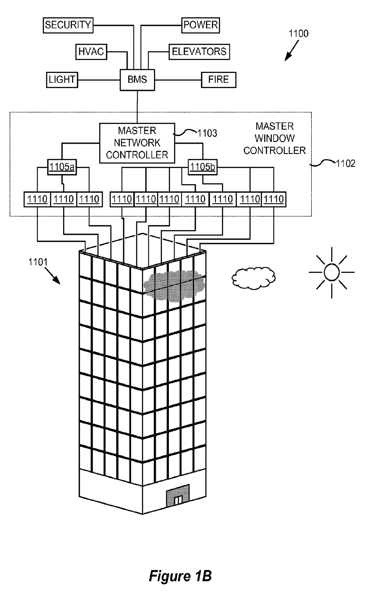
  • Monitoring sites containing switchable optical devices and controllers
  • Monitoring sites containing switchable optical devices and controllers
  • Monitoring sites containing switchable optical devices and controllers

Examples


example switching

Algorithm

[0149]To speed along optical transitions, the applied voltage is initially provided at a magnitude greater than that required to hold the device at a particular optical state in equilibrium. This approach is illustrated in FIGS. 2 and 3. FIG. 2 is a graph depicting voltage and current profiles associated with driving an electrochromic device from bleached to colored and from colored to bleached. FIG. 3 is a graph depicting certain voltage and current profiles associated with driving an electrochromic device from bleached to colored.

[0150]FIG. 2 shows a complete current profile and voltage profile for an electrochromic device employing a simple voltage control algorithm to cause an optical state transition cycle (coloration followed by bleaching) of an electrochromic device. In the graph, total current density (I) is represented as a function of time. As mentioned, the total current density is a combination of the ionic current density associated with an electrochromic trans...

examples

A Site Monitoring System

[0187]FIG. 8 shows an example of a dashboard for site monitoring system. The depicted view includes a row for each of multiple sites monitored by the system, with each row including a site name, its current status, and a most recent update time. The status row indicates whether or not all monitored devices and controllers in the site appear to be functioning properly. A green light may be used to indicate no problems, a red light may be used to indicate that a problem exists, and a yellow light may be used to indicate that a device or controller is trending toward a problem. One field of the view provides a link to details about the site. Thus, if the dashboard shows that there may be a problem at the site, the user can obtain pull up event logs, sensor output, window electrical responses, etc. for the site. This allows the user to drill down quickly to the precise issue while still having a high-level picture of any sites that have issues.

[0188]FIG. 9 presen...


PUM

PropertyMeasurementUnit
hold voltageaaaaaaaaaa
energyaaaaaaaaaa
temperatureaaaaaaaaaa

Abstract

A site monitoring system may analyze information from sites to determine when a device, a sensor, a controller, or other structure associated with optically switchable devices has a problem. The system may, if appropriate, act on the problem. In certain embodiments, the system learns customer / user preferences and adapts its control logic to meet the customer's goals.

Description

PRIORITY DATA[0001]This application is a continuation of and claims priority to U.S. patent application Ser. No. 15 / 123,069, titled “MONITORING SITES CONTAINING SWITCHABLE OPTICAL DEVICES AND CONTROLLERS,” filed on Sep. 1, 2016 (Attorney Docket No. VIEWP061), which is a national phase application of PCT Patent Application No. PCT / US15 / 19031, titled “MONITORING SITES CONTAINING SWITCHABLE OPTICAL DEVICES AND CONTROLLERS,” filed on Mar. 5, 2015 (Attorney Docket No. VIEWP061WO), which claims benefit of U.S. Provisional Patent Application No. 61 / 948,464, titled “MONITORING SITES CONTAINING SWITCHABLE OPTICAL DEVICES AND CONTROLLERS,” filed Mar. 5, 2014 (Attorney Docket No. VIEWP061PUS) and U.S. Provisional Patent Application No. 61 / 974,677, titled “MONITORING SITES CONTAINING SWITCHABLE OPTICAL DEVICES AND CONTROLLERS,” filed Apr. 3, 2014 (Attorney Docket No. VIEWP061P2US), which are incorporated herein by reference in their entireties and for all purposes.BACKGROUND[0002]Electrically t...

Claims


Application Information

Patent Timeline
Patent Type & Authority Applications(United States)
IPC IPC(8): G02F1/163
CPCG02F1/163E06B2009/2464E06B9/24G05B13/0265G06Q50/10G06Q10/06Y02P90/84G01R31/50G02F1/15G02B26/00G02F1/0121G02F1/167G05B15/02
Inventor SHRIVASTAVA, DHAIRYABROWN, STEPHEN CLARKMANI, VIJAY
Owner VIEW INC
Learn More