Eureka AIR delivers breakthrough ideas for toughest innovation challenges, trusted by R&D personnel around the world.

Layered three-dimensional radiation position detector

Inactive Publication Date: 2017-10-05
NAT INST FOR QUANTUM & RADIOLOGICAL SCI & TECH
View PDF0 Cites 5 Cited by
  • Summary
  • Abstract
  • Description
  • Claims
  • Application Information

AI Technical Summary

Benefits of technology

The technical problem addressed in this patent is how to improve the image quality of PET devices without using small scintillator elements, which can be difficult to identify and have manufacturing costs. Additionally, how to improve the resolution of PET devices for diagnosis and research of mental and neurotic disorders, which require high resolution compared to whole body cancer screening.

Problems solved by technology

However, such a thickness can degrade the spatial resolution with respect to obliquely-incident annihilation radiations.

Method used


Image

  • Layered three-dimensional radiation position detector
  • Layered three-dimensional radiation position detector
  • Layered three-dimensional radiation position detector

Examples


Embodiment Construction

[0041]Embodiments of the present invention will be described below in detail with reference to the drawings. It should be noted that the present invention is not limited to the contents described in the following embodiments and practical examples. The components of the embodiments and practical examples described below may include ones easily conceivable by those skilled in the art, substantially identical ones, and ones within the range of equivalency. The components disclosed in the embodiments and practical examples described below may be combined as appropriate, and may be selected and used as appropriate.

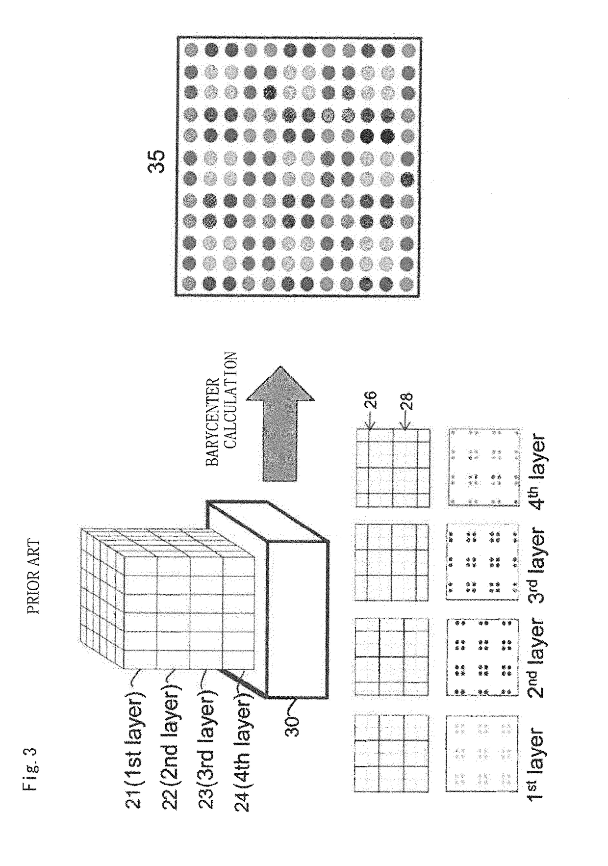
[0042]FIGS. 7A to 7E show an embodiment of the present invention which is applied to the four-layer radiation three-dimensional position detector shown in FIG. 3.

[0043]In the present embodiment, a first-layer scintillator array 31 on a radiation incident surface side has a pixel pitch ½ that of the other three layers (second, third, and fourth layers) of scintillator arrays 32...


PUM


Abstract

A layered three-dimensional radiation position detector includes two-dimensional scintillator arrays that are pixelated by optically discontinuous surfaces and stacked on a light receiving surface of a light receiving element, responses of scintillator elements detecting radiations being made identifiable on the light receiving surface to obtain a three-dimensional radiation detection position. A scintillator array lying on a radiation incident surface side has a pixel pitch smaller than that of a scintillator array lying on a light receiving element side so that the scintillator array on the radiation incident surface side has increased resolution. A layered three-dimensional radiation position detector achieving both low cost and high resolution can thus be provided.

Description

CROSS-REFERENCE TO RELATED APPLICATION[0001]The disclosure of Japanese Patent Application No. 2016-073372 filed on Mar. 31, 2016 including specifications, drawings and claims is incorporated herein by reference in its entirety.TECHNICAL FIELD[0002]The present invention relates to a layered three-dimensional radiation position detector, and more particularly to a layered three-dimensional radiation position detector suitable for use in the fields of nuclear medicine imaging such as a positron imaging device and a positron emission tomography (PET) device and radiation measurement.BACKGROUND ART[0003]A radiation position detector typically includes an array of scintillator elements (such as crystals) and a light receiving element optically coupled thereto. To enhance the spatial resolution of a PET device, the sectional sizes of the scintillator elements with respect to the incident surface of the radiations need to be reduced. The image quality of the PET device therefore depends lar...

Claims


Application Information

Patent Timeline
IPC IPC(8): G01T1/20
CPCG01T1/2002G01T1/2018G01T1/2006
Inventor YOSHIDAYAMAYA, TAIGA
Owner NAT INST FOR QUANTUM & RADIOLOGICAL SCI & TECH
Why Eureka
Eureka Blog
Learn More