
Method For Treating An Exhaust Gas

a technology for treating and exhaust gas, applied in the direction of machines/engines, electrical control, separation processes, etc., can solve the problems of oxygen sensor “drift”, affecting oxygen sensors, and affecting the performance of oxygen sensors, so as to achieve the effect of reducing the generation of nox on or in the second stage catalyst and further reducing the amount of air contaminants

Active Publication Date: 2017-10-05
POWERCELL CONTROLTEK LLC
View PDF0 Cites 2 Cited by
  • Summary
  • Abstract
  • Description
  • Claims
  • Application Information

AI Technical Summary

Benefits of technology

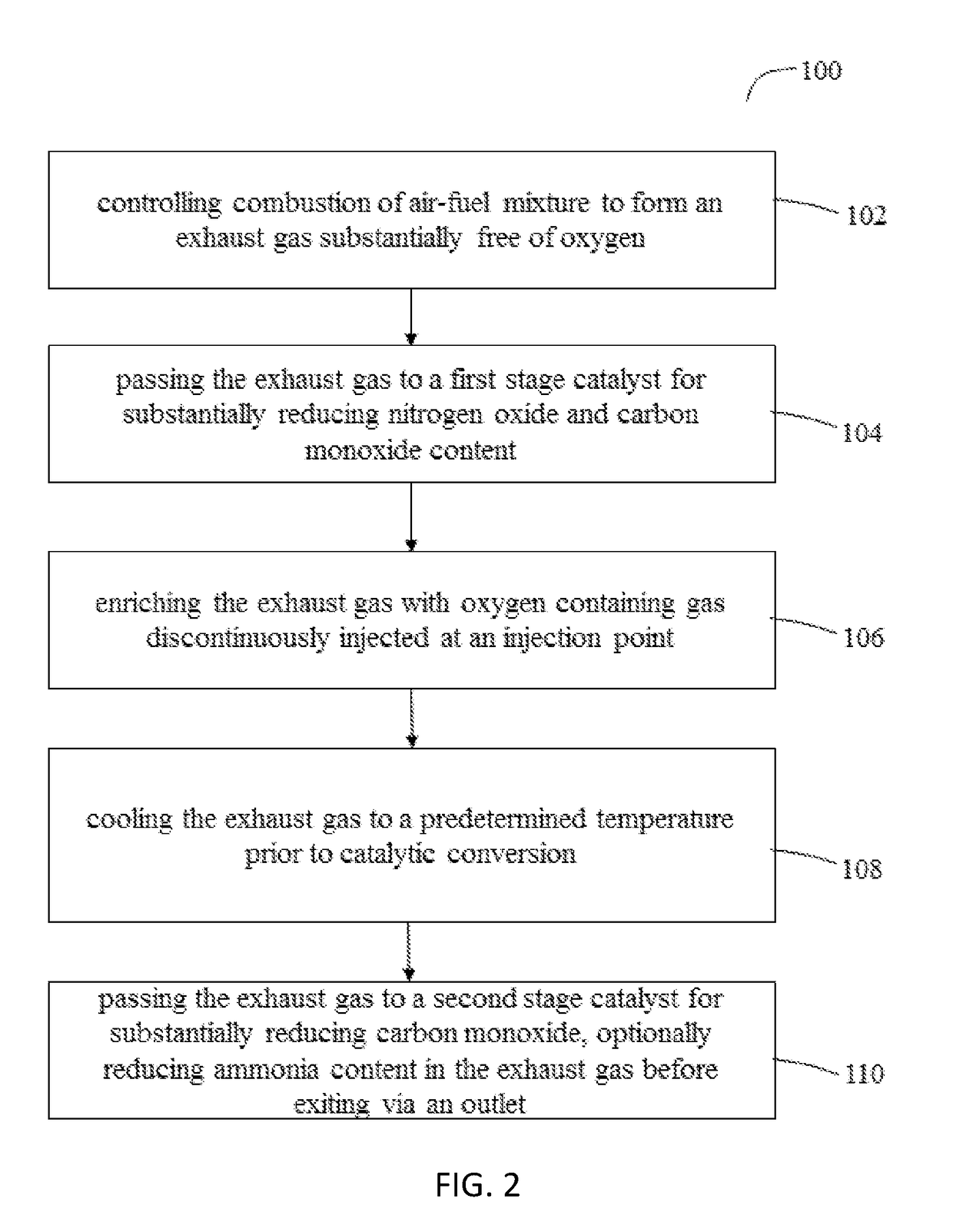
The present invention is about a method of treating exhaust gas from internal combustion engines. The method involves reducing air contaminants, cooling the exhaust, and further reducing NOx and ammonia concentrations through a second stage catalyst. This results in a treated exhaust gas with significantly reduced concentrations of NOx, carbon monoxide, and hydrocarbons. The method is especially useful for treating exhaust gas from rich-burn, spark-ignited engines.

Problems solved by technology

However, oxygen sensors can be affected by a number of factors such as exhaust temperature, engine load changes, unburned methane in the exhaust, ambient humidity, oxygen sensor age and other factors that might affect oxygen sensor output.
Oxygen sensor “drift” or incorrect oxygen sensor signal is a major cause for noncompliance with emission standards.
Oxygen sensor “drift” is a particular problem for engines that operate at variable load.
These systems have a number of disadvantages, especially for smaller engines.
Inappropriate dosing can lead to toxic ammonia emissions exceeding regulatory limits.
Further, the SCR systems can require frequent maintenance and specialized technicians.
Despite the complexity of two catalysts, these systems did not result in markedly improved emission control and, in fact, the two stage catalyst system could result in generation of NOx on or in communication with the second stage catalyst.

Method used


Image

  • Method For Treating An Exhaust Gas
  • Method For Treating An Exhaust Gas
  • Method For Treating An Exhaust Gas

Examples


Embodiment Construction

Definition of Terms

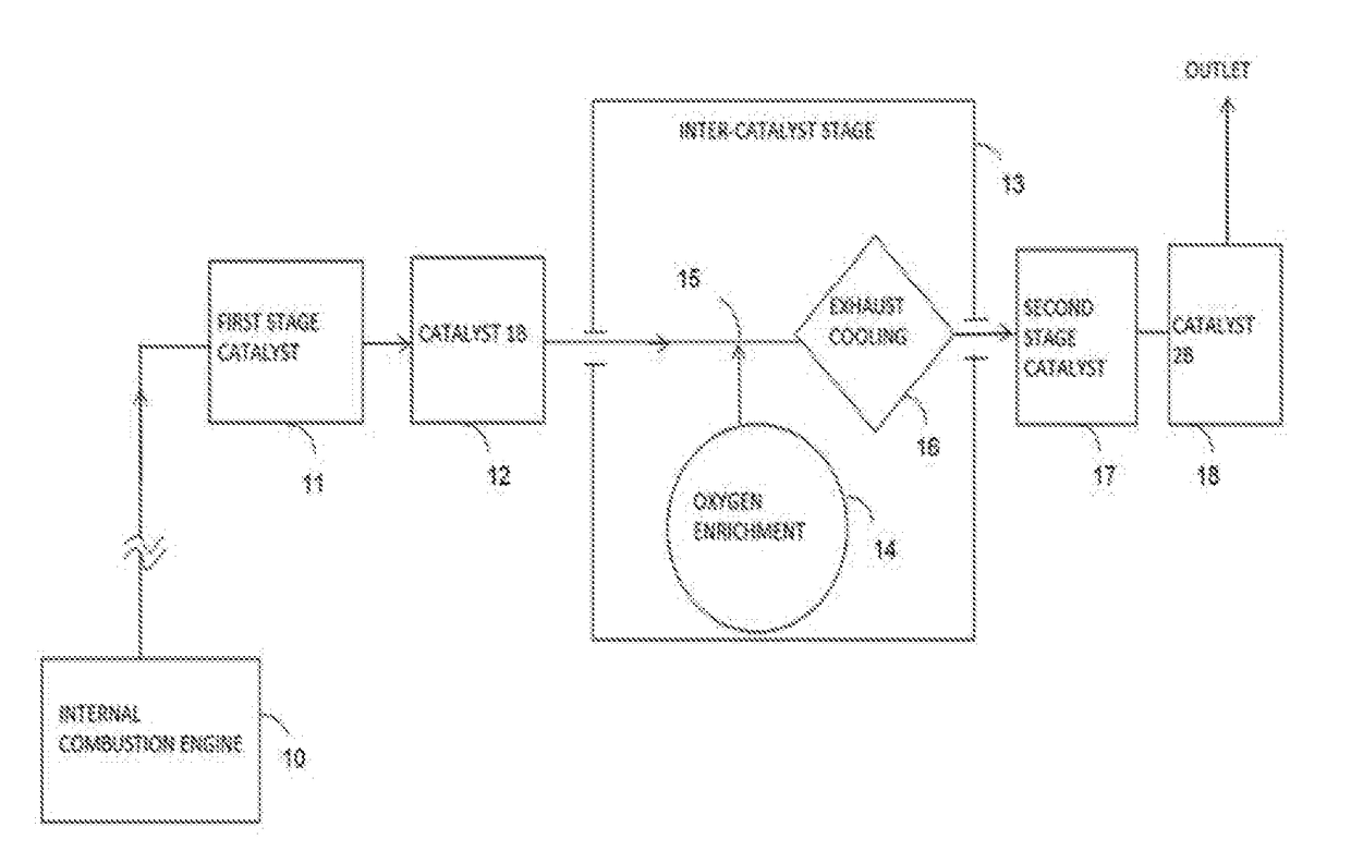
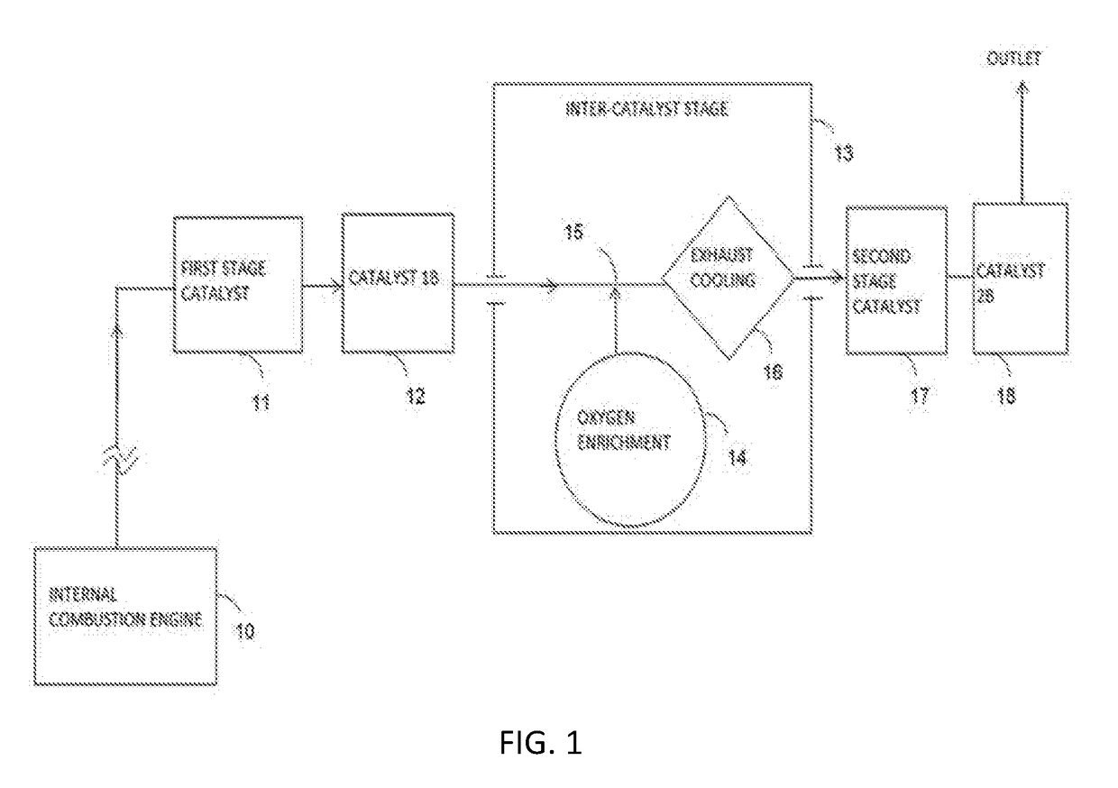
[0012]“Exhaust cooling process” refers to a device that functions to control the temperature of an exhaust gas and is located within the inter-catalyst stage.

“First stage catalyst” refers to a first catalyst in the path of an exhaust after the exhaust leaves an engine.

“Second stage catalyst” refers to a first catalyst in the path of the exhaust after an inter-catalyst stage.

“NOx” refers to nitrogen oxides including NO and NO2.

“Discontinuous” means not constant or not continuous.

“Dithering” refers to oscillating the air to fuel ratio around a set point.

“Parts per million (ppm)” refers to parts per million by volume.

“Cleaning period” refers to a period up to 30 minutes in duration.

“Inter-catalyst stage” refers to a device containing an exhaust cooling device and an oxygen enrichment device.

Oxygen containing gas” refers to a gas containing oxygen and consisting of air, oxygen gas, oxygen containing exhaust gas, or mixtures of those gases and nitrogen gas, exhaust ga...


PUM

PropertyMeasurementUnit
Temperatureaaaaaaaaaa

Abstract

A provision of assemblies and methods for treating an exhaust gas from an internal combustion engine. The treatment method comprises at least two catalyst stages. The exhaust gas is directed to a first stage catalyst. After the first stage catalyst, the exhaust is passed to an inter-catalyst stage comprising an exhaust cooling process and an oxygen enrichment process. Next, the exhaust is passed to a second stage catalyst for reducing carbon monoxide, ammonia and hydrocarbon concentration in the exhaust gas, before exiting via an outlet.

Description

CROSS-REFERENCE TO RELATED APPLICATIONS[0001]This application claims the benefit of U.S. provisional patent application Ser. No. 62 / 143,182, filed on Apr. 5, 2015, by the present inventor. This application claims the benefit of U.S. provisional patent application Ser. No. 62 / 317,425, filed on Apr. 1, 2016, by the present inventor.BACKGROUND[0002]The operation of combustion devices and particularly internal combustion (IC) engines produces small amounts of air contaminants such as carbon monoxide (CO), nitrogen oxides (NO, NO2, or generally NOx), hydrocarbons (HC) and ammonia in exhaust gas. Carbon monoxide, NOx, and ammonia are problematic air pollutants and their emission levels are regulated within certain limits in many geographical regions. NOx emissions are of particular concern. In some areas, significant NOx reductions are needed in order to meet National Ambient Air Quality Standards (NAAQS). Ammonia is a regulated toxic air contaminant and a precursor for the formation of p...

Claims


Application Information

Patent Timeline
IPC IPC(8): F01N3/20F01N3/02F01N13/00B01D53/94F02D41/02
CPCF01N3/206B01D53/9477B01D2255/904F01N13/009F01N3/02F02D41/0295B01D53/9454B01D53/9495B01D2258/012F01N3/043F01N3/101F01N3/30F02D41/1441F02D41/1454F01N3/0205F01N2270/02F01N2560/025F01N2560/14F01N2570/14F02D2250/36F01N13/0093Y02T10/12
Inventor CORLISS, II, DORIAN FRANCIS
Owner POWERCELL CONTROLTEK LLC
Learn More