
Devices and methods for minimally invasive surgery

Pending Publication Date: 2017-10-05
VISIONQUEST HLDG LLC +1
View PDF3 Cites 14 Cited by
  • Summary
  • Abstract
  • Description
  • Claims
  • Application Information

AI Technical Summary

Benefits of technology

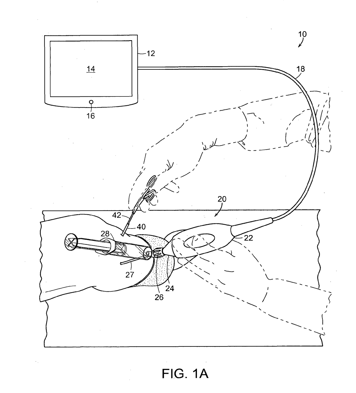
The patent describes a system and method for accessing and repairing damaged regions in the body through a joint cavity, such as the knee or hip joint. The system includes an imaging probe with an offset field of view, a cannula for positioning the imaging probe and arthroscopic tool relative to each other, and a wireless endoscopy system for broadcasting low-latency video to a receiver or computer for further processing and storage. The system also includes a high-definition camera hand-piece connected to a control unit through a multi-protocol wireless link, providing a real-time high definition imaging system that is more portable and efficient than traditional hard-wired systems.

Problems solved by technology

The acetabular labrum includes a nerve supply and as such may cause pain if damaged.
The underside of the labrum is continuous with the acetabular articular cartilage so any compressive forces that affect the labrum may also cause articular cartilage damage, particularly at the junction between the two (the chondrolabral junction).
The acetabular labrum may be damaged or torn as part of an underlying process, such as Femoroacetabular impingement (FAI) or dysplasia, or may be injured directly by a traumatic event.
Similarly, articular cartilage on the head of femur and acetabulum may be damaged or torn, for example, as a result of a trauma, a congenital condition, or just constant wear and tear.
When articular cartilage is damaged, a torn fragment may often protrude into the hip joint causing pain when the hip is flexed.
Moreover, the bone material beneath the surface may suffer from increased joint friction, which may eventually result in arthritis if left untreated.
Loose bodies may often be the result of trauma, such as a fall, an automobile accident, or a sports-related injury, or they may result from degenerative disease.
When a torn labrum rubs continuously against cartilage in the joint, this may also cause fragments to break free and enter the joint.
Loose bodies can cause a “catching” in the joint and cause both discomfort and pain.
As with all arthroscopic procedures, the hip arthroscopy is undertaken with fluid in the joint, and there is a risk that some can escape into the surrounding tissues during surgery and cause local swelling.
Moreover, the distention of the joint can result in a prolonged recovery time.
Endoscopes of smaller diameter are typically used for visual diagnostic purposes only as they cannot accommodate tools needed to perform procedures including resection and biopsy.
However, patient comfort and recovery time are both negatively affected by large diameter tools, large incisions, and multiple procedures including separate diagnostic and surgical entries.

Method used


Image

  • Devices and methods for minimally invasive surgery
  • Devices and methods for minimally invasive surgery
  • Devices and methods for minimally invasive surgery

Examples


first embodiment

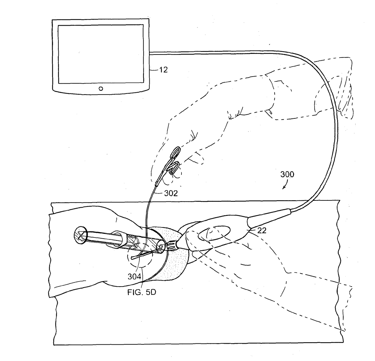
[0090]With reference now to FIG. 10A, the distal ends 1110 and 1210 of the imaging probe assembly 1100 and surgical tool assembly 1200 of FIG. 9 is depicted taken along section 10A-10A of FIG. 9. As depicted, the cannulas 27 and 40 are inserted up until the start of the curved access space 1320 between the femoral head 1302 and the acetabulum 1304 in the hip joint 1300. The sheath / endoscope 34 and the tool 42 extend / protrude from distal ends of the cannula 27 and 40 into the curved access space 1320 to reach the damaged region 1310 of the hip joint 1300. As depicted, the distal ends 1110 and 1210 of the imaging probe assembly 1100 and surgical tool assembly 1200 are shaped to substantially match the curved access space 1320. Thus, in the depicted embodiment, distal ends of the tool 42 and of the sheath / endoscope 23, 34 are curved to substantially match the curvature of the curved access space 1320.

second embodiment

[0091]With reference now to FIG. 1013, the distal ends 1110 and 1210 of the imaging probe assembly 1100 and surgical tool assembly 1200 of FIG. 9 is depicted taken along section 10B-10B of FIG. 9. Similar to the embodiment in FIG. 10A, the cannula 27 and 40 are depicted as inserted up until the start of the curved access space 1320 between the femoral head 1302 and the acetabulum 1304 in the hip joint 1300. Thus, the sheath / endoscope 34 and the tool 42 extend / protrude from distal ends of the cannula 27 and 40 into the curved access space 1320 to reach the damaged region 1310 of the hip joint 1300. As depicted, the distal ends 1110 and 1210 of the imaging probe assembly 1100 and surgical tool assembly 1200 are shaped to substantially match the curved access space 1320. Thus, in the depicted embodiment, distal ends of the tool 42 and of the sheath / endoscope 23, 34 are curved to substantially match the curvature of the curved access space 1320. In comparison with the embodiment of FIG....

third embodiment

[0092]With reference now to FIG. 10C, the distal ends 1110 and 1210 of the imaging probe assembly 1100 and surgical tool assembly 1200 of FIG. 9 is depicted taken along section 10C-10C of FIG. 9. In contrast with FIGS. 10A and 10B, the cannula 27 and 40 are depicted as inserted into the curved access space 1320 between the femoral head 1302 and the acetabulum 1304 in the hip joint 1300. Thus, the sheath / endoscope 34 and the tool 42 are substantially enclosed up to the damaged region 1310 of the hip joint 1300. As depicted, the distal ends 1110 and 1210 of the imaging probe assembly 1100 and surgical tool assembly 1200 are shaped to substantially match the curved access space 1320. Thus, in the depicted embodiment, distal ends of the cannula 27 and 40 are curved to substantially match the curvature of the curved access space 1320. Again, it will be appreciated by one of ordinary skill in the art that various geometric configurations may be utilized for accessing the curved access spa...


PUM


Abstract

The present invention relates to methods and devices for minimally invasive diagnosis and treatment of joint injuries and other injuries or diseases in body joints, tissues, and cavities. Small diameter endoscopic devices are used for visualization and to provide access for the insertion of small diameter surgical tools without the use of distending fluid. Preferred embodiments of the endoscopic devices can utilize wireless transmission to a handheld display device to visualize diagnostic and therapeutic procedures in accordance with the invention.

Description

CROSS-REFERENCE TO RELATED APPLICATIONS[0001]This application claims priority to U.S. Provisional Application No. 61 / 974,427 filed Apr. 2, 2014, U.S. Provisional Application No. 61 / 979,476 filed Apr. 14, 2014, U.S. Provisional Application No. 62 / 003,287 filed May. 27, 2014, U.S. Provisional Application No. 62 / 045,490 filed Sep. 3, 2014, and U.S. patent application Ser. No. 14 / 677,895 filed Apr. 2, 2015, the entire contents of these applications being incorporated herein by reference.BACKGROUND OF THE INVENTION[0002]The medial meniscus and lateral meniscus are crescent-shaped bands of thick, pliant cartilage attached to the shinbone (fibia). Meniscectomy is the surgical removal of all or part of a torn meniscus. The lateral meniscus is on the outside of the knee, is generally shaped like a circle, and covers 70% of the tibial plateau. The medial meniscus is on the inner side of the knee joint, has a C shape, and is thicker posteriorly. As the inner portion of the meniscus does not ha...

Claims


Application Information

Patent Timeline
IPC IPC(8): A61B1/317A61B17/16A61B1/313A61B1/04A61B1/06A61B1/07A61B17/00A61B1/018
CPCA61B1/317A61B17/00234A61B17/16A61B1/018A61B1/042A61B2017/4216A61B1/07A61B1/3132A61B2017/00221A61B2017/003A61B2017/00336A61B1/0684A61B1/00016A61B1/00052A61B1/00105A61B1/00135A61B1/00144A61B1/00167A61B1/015G02B23/2469G02B23/26
Inventor BARBATO, LOUIS J.FAVALORA, GREGG E.POMPE VAN MEERDERVOORT, HJALMARGILL, IV, THOMAS J.
Owner VISIONQUEST HLDG LLC
Learn More