
Variable magnetization machine controller

a variable magnetization machine and controller technology, applied in the direction of electric generator control, dynamo-electric converter control, dynamo-electric gear control, etc., can solve the problems of insufficient voltage supply for inverters, high voltage level induced in the control system by pulse current,

Active Publication Date: 2017-09-28
WISCONSIN ALUMNI RES FOUND +1
View PDF9 Cites 5 Cited by
  • Summary
  • Abstract
  • Description
  • Claims
  • Application Information

AI Technical Summary

Benefits of technology

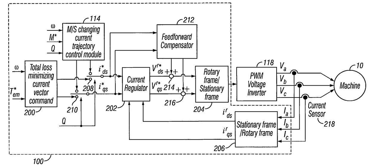
The patent text describes an improved motor control system for a variable magnetization machine that reduces the voltage induced by a pulse current to a low enough level so that the inverter can provide a sufficient voltage to drive the machine even at a high speed. The control system generates a reversely rotating d-axis / q-axis current vector trajectory during a change in a magnetization state of the machine to drive it at a predetermined speed while maintaining the driving voltage below a predetermined maximum magnitude. The technical effect is to maintain a constant driving voltage while reducing the voltage induced by a pulse current, thereby improving the motor control system's efficiency and performance at high speeds.

Problems solved by technology

However, at a high motor speed, the voltage induced in the control system by the pulse current can increase to a high voltage level.
At this high voltage level, the inverter may be no longer capable of providing enough voltage to drive the motor at the desired speed.

Method used


Image

  • Variable magnetization machine controller
  • Variable magnetization machine controller
  • Variable magnetization machine controller

Examples


Embodiment Construction

[0022]Selected embodiments will now be explained with reference to the drawings. It will be apparent to those skilled in the art from this disclosure that the following descriptions of the embodiments are provided for illustration only and not for the purpose of limiting the invention as defined by the appended claims and their equivalents.

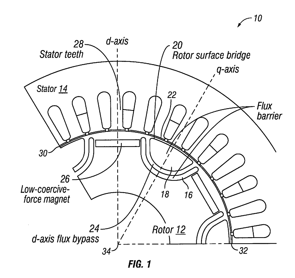
[0023]As shown in FIG. 1, a variable magnetization machine 10, which can also be referred to as a variable magnetization motor or other type of variable flux machine, includes a rotor 12 and a stator 14. As discussed herein, the terms variable magnetization machine and variable flux machine can be used synonymously to refer to the same type of machine. The variable magnetization machine 10 can be employed in any type of electric vehicle or HEV such as an automobile, truck, SUV and so on, and in any other type of apparatus as understood in the art. The rotor 12 and the stator 14 can be made of metal or any other suitable material as understood in t...


PUM


Abstract

A variable magnetization machine control system comprising a controller configured to generate a reversely rotating d-axis / q-axis current vector trajectory during a change in a magnetization state of a variable magnetization machine to drive the variable magnetization machine at a predetermined speed while maintaining the driving voltage below a predetermined maximum magnitude.

Description

CROSS-REFERENCE TO RELATED APPLICATION[0001]Related subject matter is disclosed in International Application No. PCT / US2013 / 048562, filed on Jun. 28, 2013, and an International Application entitled “Variable Magnetization Machine Controller,” (Attorney Docket No. NS-WO145203), filed concurrently herewith, the entire contents both of these International Applications being incorporated by reference herein.BACKGROUNDField of the Invention[0002]The present invention generally relates to a variable magnetization machine controller. More particularly, the present invention relates to a controller that is able to reduce the voltage induced by a pulse current to control a variable magnetization machine, such as an electric motor or other type of variable flux machine, that is employed in an electric or hybrid electric vehicle, at the reduced voltage.Background Information[0003]Electric vehicles and hybrid electric vehicles (HEV) include an electric motor that operates as a drive source for ...

Claims


Application Information

Patent Timeline
Patent Type & Authority Applications(United States)
IPC IPC(8): H02P21/06B60L15/02H02P21/22
CPCH02P21/06H02P21/22Y02T10/643H02P2101/45B60L15/025H02P27/12H02P21/0003H02P21/0085H02P21/0021Y02T10/64
Inventor FUKUSHIGE, TAKASHIGAGAS, BRENT S.YU, CHEN-YENLORENZ, ROBERT D.
Owner WISCONSIN ALUMNI RES FOUND
Learn More