
Composite constructed floating submersible water supply pump

a submerged pump and composite technology, applied in the direction of mechanical equipment, machines/engines, liquid fuel engines, etc., can solve the problems of galvanic corrosion of aluminum body pumps, and without use, the aluminum surface of coating technologies, such as hard-coat anodization and polyester powder coating, are stripped from the aluminum surface, etc., to achieve strong, durable and lightweight pump casings, the effect of sacrificing material strength and durability

Inactive Publication Date: 2017-09-21
CHIEF TECH
View PDF1 Cites 3 Cited by
  • Summary
  • Abstract
  • Description
  • Claims
  • Application Information

AI Technical Summary

Benefits of technology

The invention is a water supply pump that is made up of a strong and durable casing and impeller. The pump is made from a composite material that is very lightweight and strong, eliminating corrosion and pitting caused by silted water. The composite casing is reinforced with fiber materials like glass or carbon, and the impeller is made from an isotropic fiber reinforced composite. This design allows for easy and rapid deployment in high-volume water systems.

Problems solved by technology

Additionally, aluminum body pumps suffer from galvanic corrosion (without the use of sacrificial anodes) and pitting from highly silted shallow water.
Moreover, coating technologies, like hard-coat anodization and polyester powdercoating, are stripped from the aluminum surface during pumping operations because of the abrasive qualities of such heavily silted waters.

Method used


Image

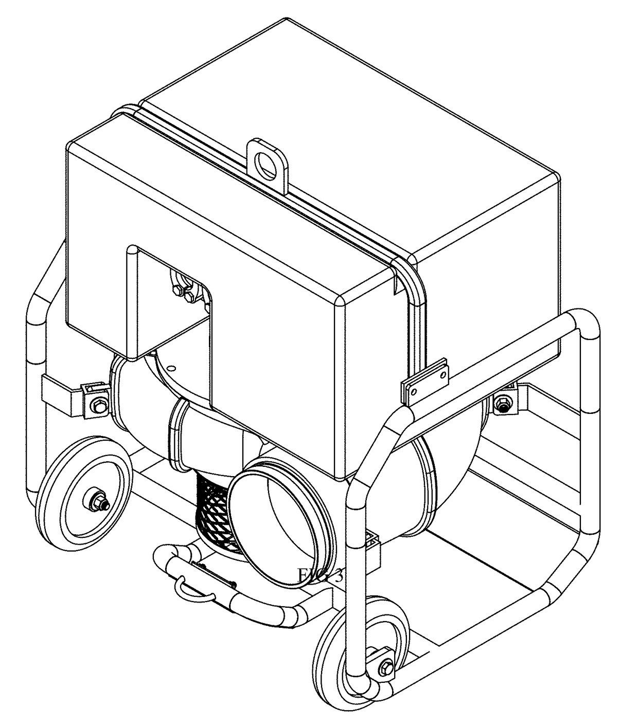
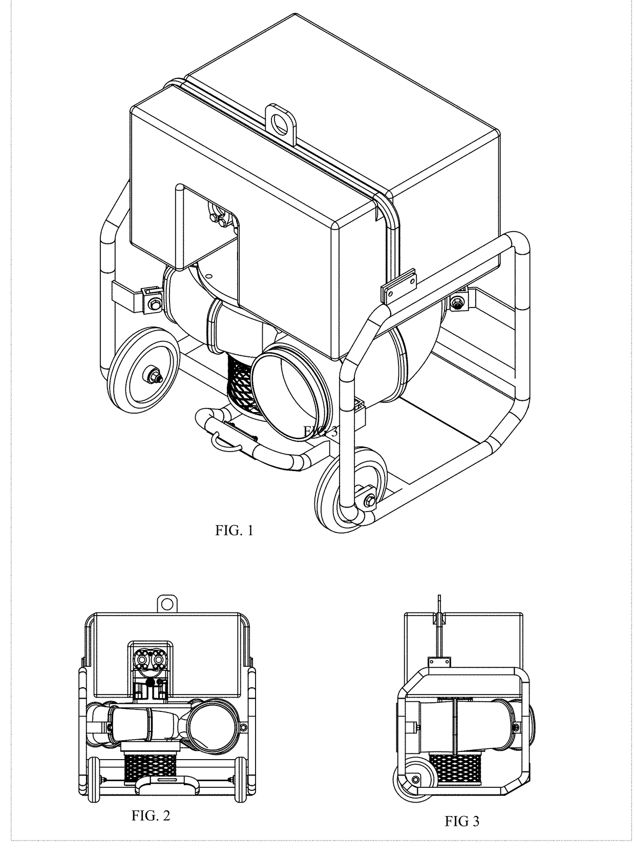
  • Composite constructed floating submersible water supply pump
  • Composite constructed floating submersible water supply pump
  • Composite constructed floating submersible water supply pump

Examples


Embodiment Construction

[0012]The composite constructed floating submersible water supply pump is specifically designed to be ultra-lightweight (comparable to other traditional metal technologies) and highly corrosion resistant to saline environments. By providing such a lightweight system, rapid system deployment for high-volume water transfer needs (such as in municipal de-flooding, FIG. 7) is made possible without the use of heavy equipment, instead substituted by manual manpower.

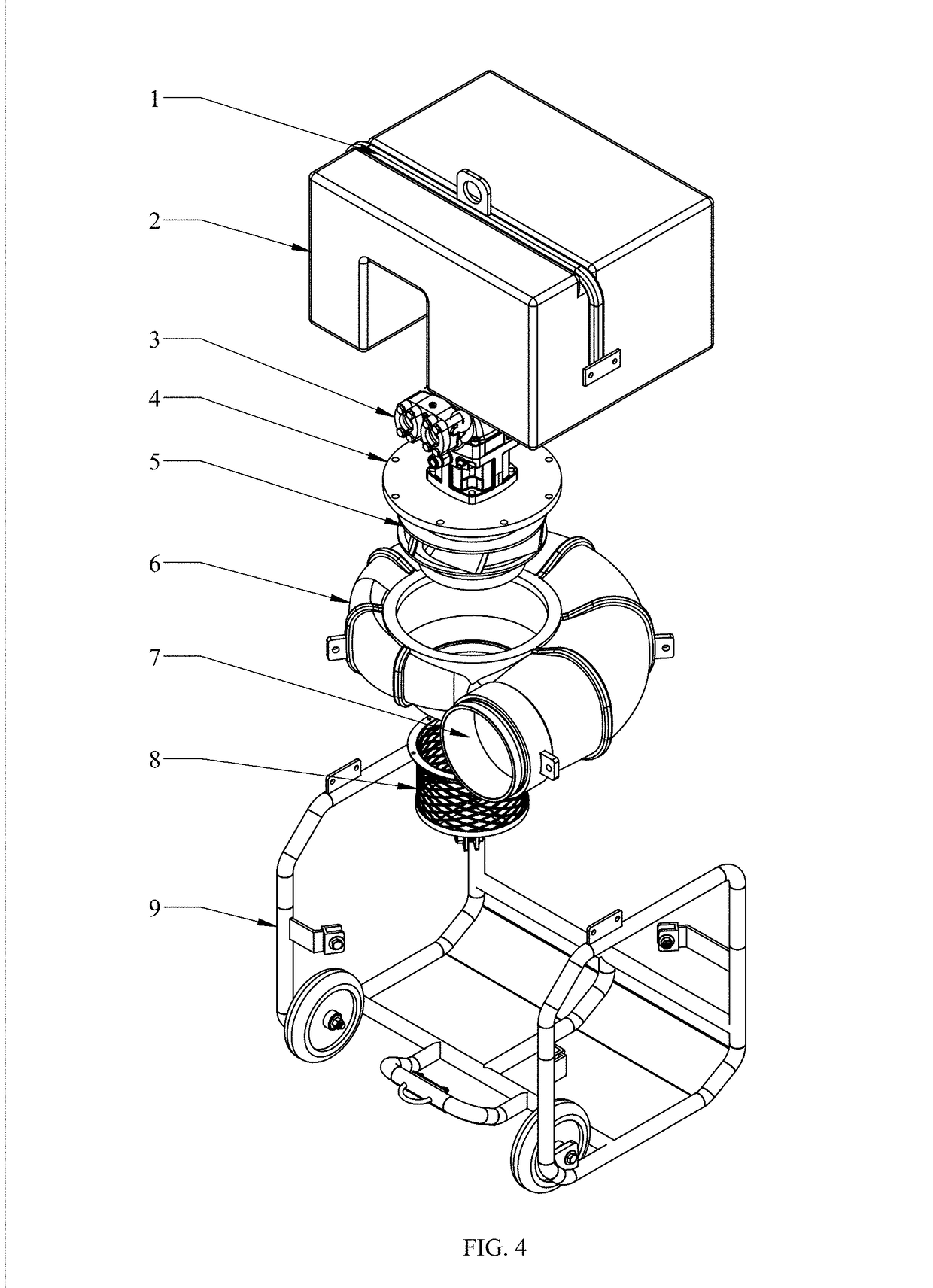
[0013]The composite floating submersible pump is manufactured using well understood commercial manufacturing concepts and intuitive tooling systems. The integral pontoon (FIG. 4, item 2) is made through rotational molding using economical thermoplastic polymers. The same pontoon can also be constructed from typical fiberglass hand layup methods. The motor (FIG. 4, item 3) is a standard commercially available hydraulic or electric motor capable of running submerged in water. The motor external body is sealed, and the surface is ...


PUM

PropertyMeasurementUnit
Weightaaaaaaaaaa
Weight ratioaaaaaaaaaa
Strengthaaaaaaaaaa

Abstract

The disclosure describes the improvement of mobile floating submersible pump systems where such systems are used for rapid deployment water transfer. Such systems are deployed within industrial fire fighting, flood control operations (FIG. 7) and similar water transfer requirements. A floating submersible pump is designed to separate the power system (FIG. 7, item 11), such as a diesel engine, from the pump body (FIG. 7, item 16), which further enables the operator to deploy a pumping system where traditional ground based centrifugal pumps are unable to physically siphon the water. Floating submersible pump systems are cumbersome in nature, requiring heavy equipment and significant manpower to deploy them. The innovation disclosed uses advancements in structural fiber reinforced materials to drastically reduce the weight of such systems, which removes the need for heavy deployment equipment, with the added benefit of corrosion protection from saline environments through the use of chemically inert composites.

Description

BACKGROUND OF THE INVENTION[0001]Municipal and emergency water requirements are frequently mismatched with improper sourcing equipment for rapid deployment and delivery of high-volume water. For example, a typical firetruck is incapable of drafting (i.e. siphoning) water from an open water source (such as a lake or pond) much more than 10 feet below its pump's center-line. This is a common problem of all pumps (most notably centrifugal) as water begins to vaporize within the pump intake under extended suction ranges, causing severe cavitation damage. This is governed by the Net Positive Suction Head Principle; the difference between the pump suction head pressure and the pumping medium vapor pressure at a given operating temperature. Fixed pumping systems, such as that found within a building or refinery, use flooded intakes (often further pressurized by municipal water mains) that alleviate this problem. Additionally, a fire truck may have access to a pressurized hydrant system pro...

Claims


Application Information

Patent Timeline
IPC IPC(8): F04D29/02F04D29/42F04D29/22F04D1/00F04D7/06
CPCF04D29/026F04D1/00F04D7/06F04D13/08F04D29/426F04D13/04F04D29/22F05D2300/44F04D13/02F04D13/066F04D29/2205F05D2300/6031
Inventor CHANDLER, KYLE VICTOR
Owner CHIEF TECH
Learn More