Engine bleed system with motorized compressor

a technology of motorized compressors and bleed systems, which is applied in the direction of machines/engines, energy-saving board measures, and efficient propulsion technologies. it can solve the problems of reducing engine efficiency, excessive hotness, and high pressure air typically ho

Active Publication Date: 2017-09-21
HAMILTON SUNDSTRAND CORP
View PDF11 Cites 16 Cited by
  • Summary
  • Abstract
  • Description
  • Claims
  • Application Information

AI Technical Summary

Benefits of technology

[0004]According to another embodiment, an engine bleed control system for a gas turbine engine of an aircraft is provided. The engine bleed control system includes an engine bleed tap coupled to a compressor source of a lower pressure compressor section before a highest pressure compressor section of the gas turbine engine and a motorized compressor in fluid communication with the engine bleed tap. The engine bleed control system also includes a controller operable to selectively drive the motorized compressor to boost a bleed air pressure from the compressor source as pressure augmented bleed air and control delivery of the pressure augmented bleed air to an aircraft use.
[0002]Gas turbine engines are used in numerous applications, one of which is for providing thrust to an aircraft. Compressed air is typically tapped at a high pressure location near the combustor for auxiliary uses, such as environmental control of the aircraft. However, this high pressure air is typically hotter than can safely be supported by ductwork and delivery to the aircraft. Thus, a pre-cooler or heat exchanger is used to cool high-temperature engine bleed air and is typically located near the engine such that excessively hot air is not ducted through the wing of the aircraft for safety reasons. Diverting higher pressure and higher temperature air from the engine beyond the pressure needed reduces engine efficiency. Further, heat exchangers used to cool engine bleed air add to overall aircraft weight, which also reduces fuel burn efficiency.
[0005]According to a further embodiment, a method of controlling an engine bleed system for a gas turbine engine of an aircraft is provided. The method includes establishing fluid communication between a motorized compressor and an engine bleed tap at a fan-air source or a compressor source of a lower pressure compressor section before a highest pressure compressor section of the gas turbine engine. The motorized compressor is selectively driven to boost a bleed air pressure from the engine bleed tap as pressure augmented bleed air. Delivery of the pressure augmented bleed air to an aircraft use is controlled.
[0004]According to another embodiment, an engine bleed control system for a gas turbine engine of an aircraft is provided. The engine bleed control system includes an engine bleed tap coupled to a compressor source of a lower pressure compressor section before a highest pressure compressor section of the gas turbine engine and a motorized compressor in fluid communication with the engine bleed tap. The engine bleed control system also includes a controller operable to selectively drive the motorized compressor to boost a bleed air pressure from the compressor source as pressure augmented bleed air and control delivery of the pressure augmented bleed air to an aircraft use.
[0004]According to another embodiment, an engine bleed control system for a gas turbine engine of an aircraft is provided. The engine bleed control system includes an engine bleed tap coupled to a compressor source of a lower pressure compressor section before a highest pressure compressor section of the gas turbine engine and a motorized compressor in fluid communication with the engine bleed tap. The engine bleed control system also includes a controller operable to selectively drive the motorized compressor to boost a bleed air pressure from the compressor source as pressure augmented bleed air and control delivery of the pressure augmented bleed air to an aircraft use.

Problems solved by technology

However, this high pressure air is typically hotter than can safely be supported by ductwork and delivery to the aircraft.
Thus, a pre-cooler or heat exchanger is used to cool high-temperature engine bleed air and is typically located near the engine such that excessively hot air is not ducted through the wing of the aircraft for safety reasons.
Diverting higher pressure and higher temperature air from the engine beyond the pressure needed reduces engine efficiency.
Further, heat exchangers used to cool engine bleed air add to overall aircraft weight, which also reduces fuel burn efficiency.

Method used


Image

  • Engine bleed system with motorized compressor
  • Engine bleed system with motorized compressor
  • Engine bleed system with motorized compressor

Examples


Embodiment Construction

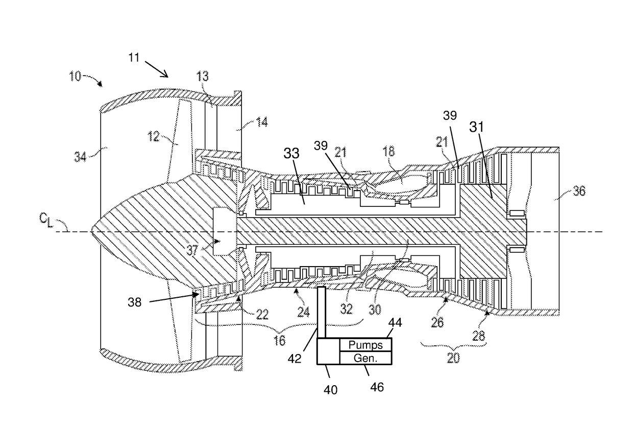
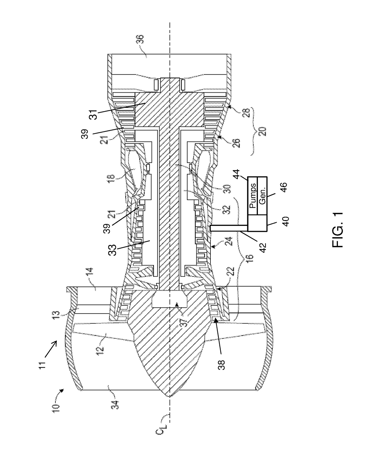
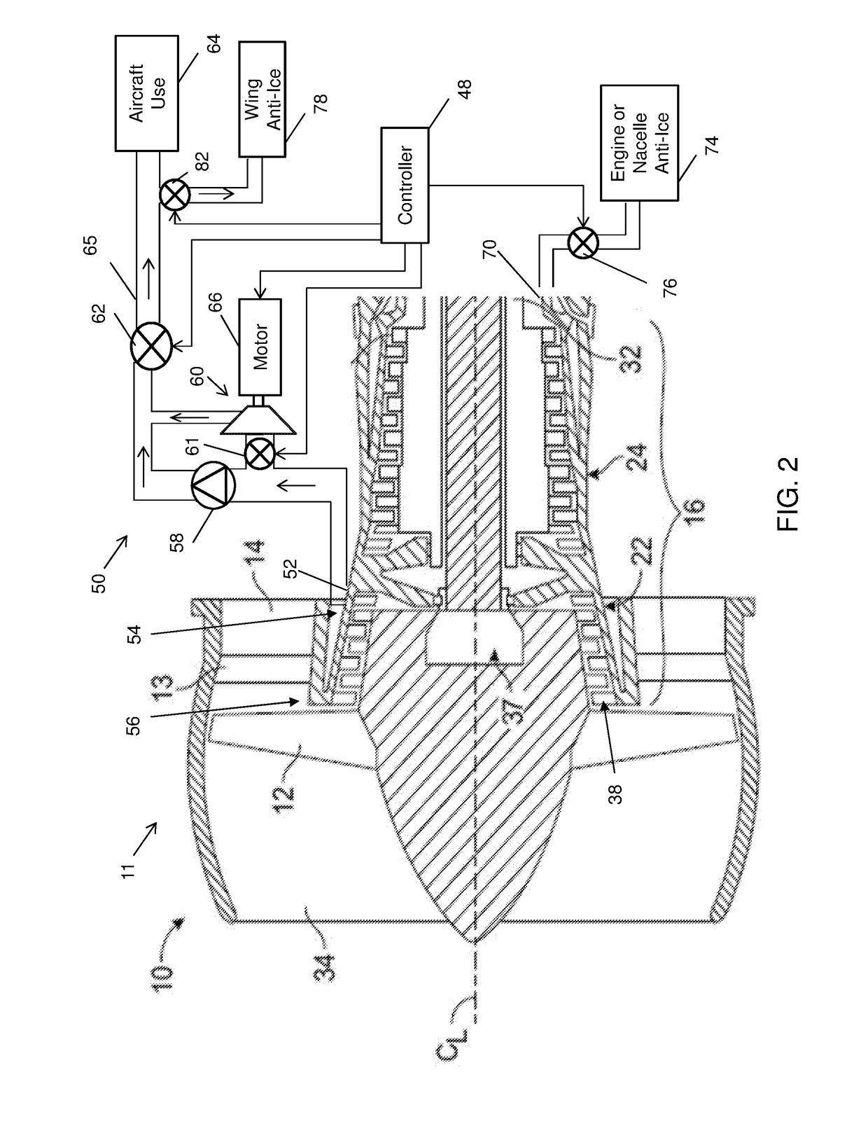
[0013]Various embodiments of the present disclosure are related to engine bleed control for a gas turbine engine. Embodiments of this disclosure may be applied on any turbomachinery from which compressed air is tapped off for auxiliary uses. For example, gas turbine engines are rotary-type combustion turbine engines built around a power core made up of a compressor, combustor and turbine, arranged in flow series with an upstream inlet and downstream exhaust. The compressor compresses air from the inlet, which is mixed with fuel in the combustor and ignited to generate hot combustion gas. The turbine extracts energy from the expanding combustion gas, and drives the compressor via a common shaft. Energy is delivered in the form of rotational energy in the shaft, reactive thrust from the exhaust, or both. Compressed air can be extracted from various stages as bleed air.

[0014]Gas turbine engines provide efficient, reliable power for a wide range of applications, including aviation and i...


PUM


Abstract

An engine bleed control system for a gas turbine engine of an aircraft is provided. The engine bleed control system includes an engine bleed tap coupled to a fan-air source or a compressor source of a lower pressure compressor section before a highest pressure compressor section of the gas turbine engine and a motorized compressor in fluid communication with the engine bleed tap. The engine bleed control system also includes a controller operable to selectively drive the motorized compressor to boost a bleed air pressure as pressure augmented bleed air and control delivery of the pressure augmented bleed air to an aircraft use.

Description

BACKGROUND[0001]This disclosure relates to gas turbine engines, and more particularly to an engine bleed system with a motorized compressor.[0002]Gas turbine engines are used in numerous applications, one of which is for providing thrust to an aircraft. Compressed air is typically tapped at a high pressure location near the combustor for auxiliary uses, such as environmental control of the aircraft. However, this high pressure air is typically hotter than can safely be supported by ductwork and delivery to the aircraft. Thus, a pre-cooler or heat exchanger is used to cool high-temperature engine bleed air and is typically located near the engine such that excessively hot air is not ducted through the wing of the aircraft for safety reasons. Diverting higher pressure and higher temperature air from the engine beyond the pressure needed reduces engine efficiency. Further, heat exchangers used to cool engine bleed air add to overall aircraft weight, which also reduces fuel burn efficie...

Claims


Application Information

Patent Timeline
Patent Type & Authority Applications(United States)
IPC IPC(8): F02C6/08B64D13/00B64D15/04B64D33/02F02C3/04H02K7/18
CPCF02C6/08F02C3/04H02K7/1823B64D2033/0233B64D33/02B64D13/00B64D15/04F02C7/047F02C7/057B64D15/02F02K3/06F02C9/18F05D2270/3013F05D2270/303F05D2270/07Y02T50/60Y02T50/50
Inventor SCHWARZ, FREDERICK M.
Owner HAMILTON SUNDSTRAND CORP
Why Eureka
Try Eureka