Electrical storage system comprising a disc-shaped discrete element, discrete element, method for the production thereof, and use thereof

a technology of disc-shaped discrete elements and storage systems, which is applied in the direction of cell components, final product manufacturing, sustainable manufacturing/processing, etc., can solve the problems of affecting the production efficiency of the product, the use of substrate materials, and the inability to meet the requirements of the production process, so as to achieve the effect of avoiding production rejects, high uniform thickness distribution, and saving costs

Active Publication Date: 2017-09-14
SCHOTT AG
View PDF1 Cites 1 Cited by
  • Summary
  • Abstract
  • Description
  • Claims
  • Application Information

AI Technical Summary

Benefits of technology

[0033]The high uniformity of the thickness distribution of the sheet-type discrete element is essential for keeping a consistent quality from cell to cell. Thin film batteries are mostly manufactured at wafer level, with or without masking, and are then cut out. In the case of insufficient thickness consistency, the cells on a wafer or at least from wafer to wafer might have different thicknesses and hence different specifications, e.g. with respect to weight / energy density. This is disadvantageous in particular when the application requires an extremely homogeneous consistency of the product specifications of the electrical storage element. With a low total thickness variation, costs can be saved in quality inspection and production rejects can be avoided.
[0034]If the sheet-type discrete element is used as a substrate for the deposition of a thin film storage element, a further result of the high uniformity of the thickness distribution is that the layers are deposited evenly and without lateral variation of the layer thickness distribution. This in turn leads to the situation that in case of subsequent process steps, for example annealing of the LCO layer after deposition thereof, local stresses in the individual layers or between the individual layers at the respective interfaces are prevented, in particular also at the interfaces between layer and substrate. In this way, cracks and detachments are efficiently avoided.

Problems solved by technology

However, the latter are inflammable and lead to safety concerns regarding the use of the cited lithium-ion batteries.
In case of lithium-based thin film storage elements, particular difficulties are moreover encountered due to the use of metallic lithium as an anode material because of the high reactivity thereof.
In addition, as described in document US 2010 / 0104942 A1 by way of example, under the manufacturing conditions of a lithium-based thin film storage element, in particular during so-called annealing or heat treatment steps which are necessary for the formation of crystal structures suitable for lithium intercalation, undesirable side reactions of the mobile lithium ions with the substrate will occur, since the lithium has a high mobility and can easily diffuse into common substrate materials.
A further issue with thin film storage elements relates to the substrate materials employed.
This is due to the fact that for producing a cathode from the usually employed lithium cobalt oxide (LCO), a temperature treatment at temperatures of 500° C. and more is necessary in order to obtain a crystal structure that is particularly favorable for storing Li+ ions in this material, so that materials such as polymers or inorganic materials with low softening points cannot be used.
For example, dielectric materials are usually brittle and cannot be used in cost-efficient roll-to-roll processes, while metals or metal alloys, on the other hand, tend to oxidize during a high-temperature treatment of the cathode material.
In general, however, such process engineering adaptations are expensive and, depending on the processing, are hardly implementable in a cost-effective manner, especially if in-line coating of wafers is envisaged.
Even small unevenness of the surface may have a critical adverse effect on the functional layers of the thin film storage element and may thus result in failure of the battery as a whole.
In summary, problems of conventional thin film storage elements are related to the corrosion susceptibility of the employed materials, in particular if metallic lithium is used, which implies complex layer structures and hence causes high costs, and are also related to the type of the substrate which should in particular be non-conductive but flexible, should exhibit high temperature resistance and should preferably be inert to the functional layers of the storage element used, and moreover should allow for deposition of layers preferably free of defects and with good layer adhesion on the substrate.
However, it has been found that even with substrates that have a particularly low surface roughness such as the glass film proposed in US 2012 / 0040211 A1, for example, failure of layers occurs as a result of cracks and / or detachment of the layers, as described in US 2014 / 0030449 A1 for example.
The method for avoiding high annealing temperatures proposed therein, namely by applying a bias voltage when creating the lithium cobalt oxide layer, however, is difficult to implement in the common in-line processes for producing thin film storage elements, as already described above, so that from a process engineering point of view it is more favorable to use a substrate that has an appropriately high temperature resistance.
Another problem that is inherent to all substrate materials regardless of their exact composition relates to one of the possible handling solutions of ultra-thin glass.
The debonding often provokes the occurrence of torsional stresses in the substrate, which stresses may furthermore be transferred to the layers deposited on the substrate, which also leads to cracks and detachment of the layers, so that as a result the layer defects caused by thickness variations of the substrate may further aggravate.
This is disadvantageous in particular when the application requires an extremely homogeneous consistency of the product specifications of the electrical storage element.

Method used


Image

  • Electrical storage system comprising a disc-shaped discrete element, discrete element, method for the production thereof, and use thereof
  • Electrical storage system comprising a disc-shaped discrete element, discrete element, method for the production thereof, and use thereof
  • Electrical storage system comprising a disc-shaped discrete element, discrete element, method for the production thereof, and use thereof

Examples


Embodiment Construction

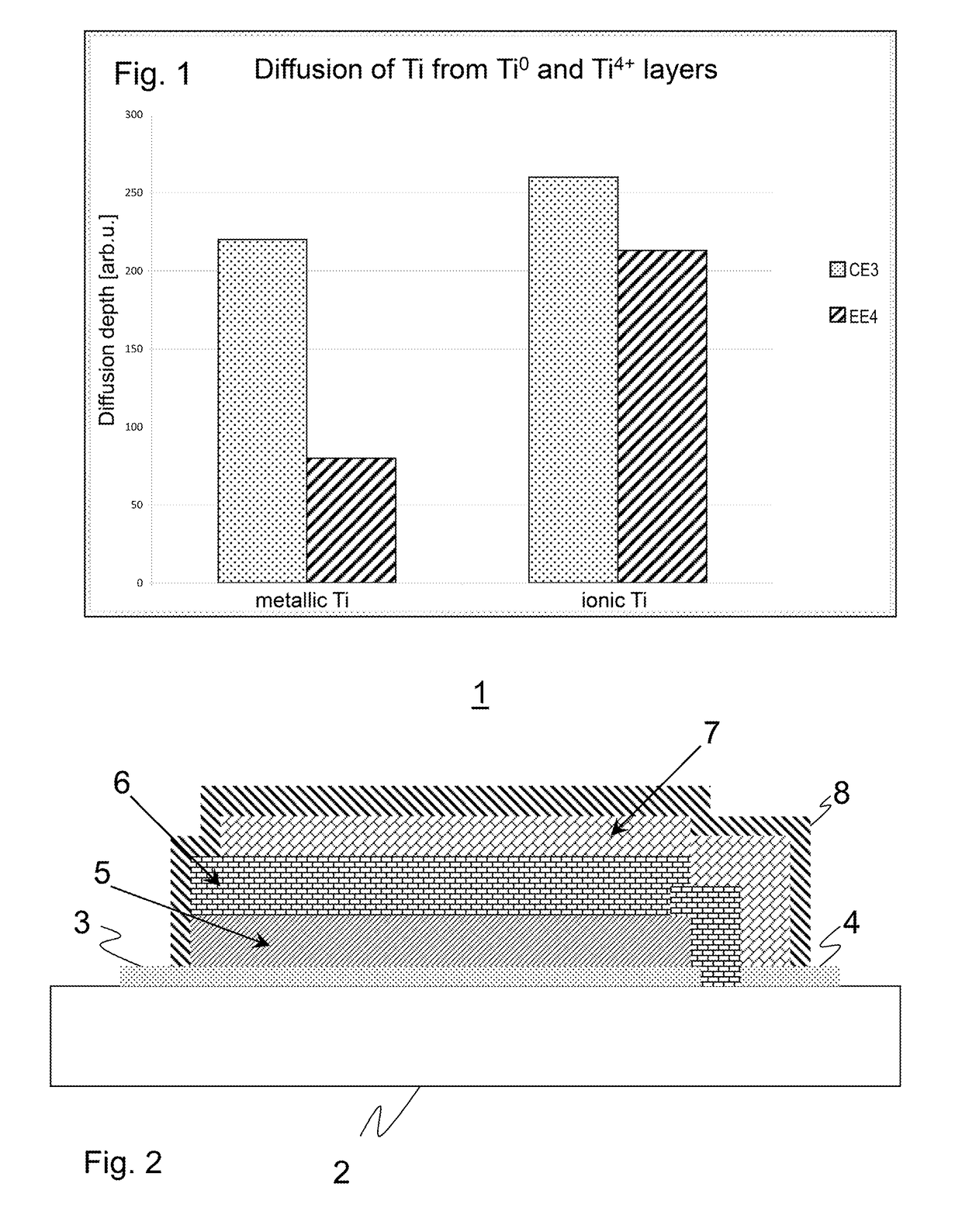
[0108]FIG. 1 shows a diagram for illustrating the influence of the TiO2 content of the sheet-type discrete element on the diffusion of metallic titanium and ionic titanium. The penetration depth of titanium is shown in arbitrary units (arb.u.) in each case, at the left for metallic titanium, at the right for ionic titanium. The composition of the sheet-type discrete elements corresponds to Exemplary Embodiment 4 and to Comparative Example 3, respectively, of table 1. The two examples differ in that Comparative Example 3 does not contain TiO2, in contrast to Exemplary Embodiment 4. With regard to titanium diffusion, the penetration depth in the titanium-containing sheet-type discrete element is significantly reduced, for both the case of metallic exposure and for the ionic exposure to TiO2.

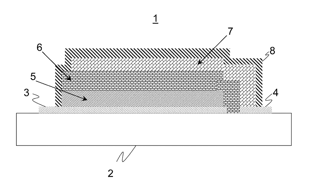
[0109]FIG. 2 schematically shows an electrical storage system 1 according to the present invention. It comprises a sheet-type discrete element 2 which is used as a substrate. A sequence of differen...


PUM

PropertyMeasurementUnit
diameteraaaaaaaaaa
thicknessaaaaaaaaaa
thicknessaaaaaaaaaa

Abstract

An electrical storage system is provided that has a thickness of less than 2 mm, which includes at least one sheet-type discrete element. The sheet-type discrete element exhibits high resistance against an attack of transition metals or transition metal ions, in particular titanium, wherein the sheet-type discrete element contains titanium. The invention also relates to a sheet-type discrete element for use in an electrical storage system, which exhibits high resistance to the attack of transition metals or of transition metal ions, in particular titanium.

Description

CROSS REFERENCE TO RELATED APPLICATIONS[0001]This application is a continuation of International Application No. PCT / EP2015 / 077799 filed on Nov. 26, 2015, which claims the benefit under 35 U.S.C. 119 of German Application No. 102014117640.5 filed on Dec. 1, 2014, the entire contents of both of which are incorporated by reference herein.BACKGROUND[0002]1. Field of the Invention[0003]The present disclosure relates to electrical storage system comprising a sheet-type discrete element, discrete element, method for the production thereof, and use thereof.[0004]2. Related Art[0005]Electrical storage systems have long been state of the art and include in particular batteries, but also so-called supercapacitors, short supercaps. In particular so-called lithium-ion batteries are being discussed in the field of novel applications such as electromobility because of the high energy densities that can be realized with them, but they have already been used for a number of years in portable device...

Claims


Application Information

Patent Timeline
Patent Type & Authority Applications(United States)
IPC IPC(8): H01M10/04H01M10/0585C03C3/097C03C3/095C03C4/20C03C3/091C03C3/087C03C3/064C03C3/066H01M10/0525C03C3/093H01M50/117H01M50/133H01M50/141
CPCH01M10/0436H01M10/0525H01M10/0585C03C3/097C03C3/095C03C4/20C03C3/091C03C3/087C03C3/064C03C3/066C03C3/093H01M50/117H01M50/141H01M50/133C03C3/085Y02E60/10Y02P70/50
Inventor PEUCHERT, ULRICHLIEBALD, RAINERKUNZE, MIRIAMDAMM, THORSTENOTTERMANN, CLEMENSSCHULTZ, NIKOLAUS
Owner SCHOTT AG
Why Eureka
Try Eureka