
Fuel cell system and control method of the same

a fuel cell and control method technology, applied in the direction of fuel cells, fuel cell details, electrical apparatus, etc., can solve the problems of reducing the amount of power generation by the fuel cell stack, and reducing the amount of overshoo

Inactive Publication Date: 2017-09-14
TOYOTA JIDOSHA KK
View PDF1 Cites 2 Cited by
  • Summary
  • Abstract
  • Description
  • Claims
  • Application Information

AI Technical Summary

Benefits of technology

The present invention relates to a fuel cell system that includes a turbo compressor. The fuel cell system uses a pressure regulation valve to control the flow of cathode gas to the fuel cell stack. The system determines an acceptable level of overshoot in the flow rate of the cathode gas based on the required power output. The system then adjusts the opening position of the pressure regulation valve to minimize the overshoot level. This helps to prevent damage to the fuel cell stack and ensures optimal performance. Additionally, the system takes into account various parameters, such as cooling water temperature and fuel cell stack impedance, to further improve the control of the pressure regulation valve. The technical effects of this invention are to reduce the overshoot in the flow rate of the cathode gas, prevent excessive drying of the fuel cell stack, and maintain optimal performance of the fuel cell system.

Problems solved by technology

Even the response correction of the rotation speed of the compressor is thus likely to fail in effectively adjusting the flow rate and to provide an excessive overshoot in the flow rate of the cathode gas.
This configuration increases the supply rate of the cathode gas and thereby rapidly increases the amount of power generation by the fuel cell stack.

Method used


Image

  • Fuel cell system and control method of the same
  • Fuel cell system and control method of the same
  • Fuel cell system and control method of the same

Examples


first embodiment

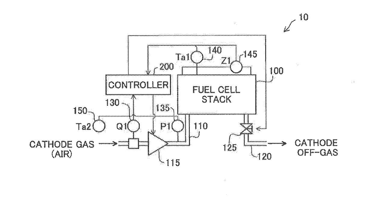
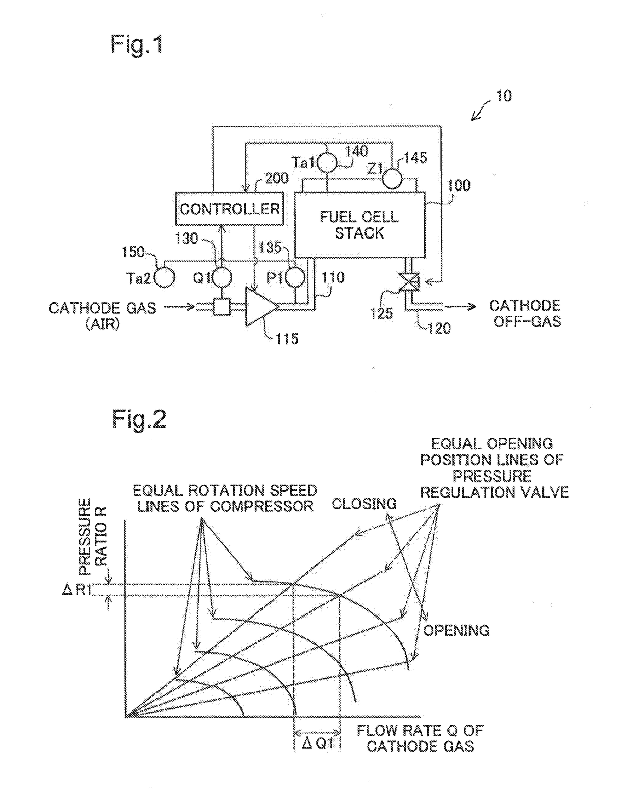
[0029]FIG. 1 is a diagram schematically illustrating a cathode gas system in a fuel cell system 10. The fuel cell system 10 is mounted on a moving body, such as a vehicle. The fuel cell system 10 may include a fuel cell stack 100, a cathode gas supply line 110, a cathode off-gas line 120, a turbo-type compressor 115 (hereinafter called “turbo compressor 115”), a pressure regulation valve 125, a flowmeter 130, a pressure sensor 135, a temperature sensor 140 and an impedance sensor 145 for the fuel cell stack 100, an ambient temperature sensor 150 and a controller 200. The turbo compressor 115 is provided in the cathode gas supply line 110 and is configured to supply the air as a cathode gas through the cathode gas supply line 110 to the fuel cell stack 100. The pressure regulation valve 125 is provided in the cathode off-gas line 120 and is configured to regulate the pressure of the cathode gas in the fuel cell stack 100. The flowmeter 130 is configured to measure flow rate Q1 of the...

second embodiment

[0052]FIG. 10 is a graph showing changes in rotation speed N of the turbo compressor 115, opening position V of the pressure regulation valve 125 and flow rate Q of the cathode gas in a second control according to a second embodiment. The second embodiment has a similar system configuration and a similar processing procedure to those of the first embodiment and differs from the first embodiment only by a time change in the opening position V of the pressure regulation valve 125 in the second control. In the second control of the first embodiment (shown in FIG. 6), the controller 200 sets the time change in the opening position V of the pressure regulation valve 125 such as to decrease the opening position V of the pressure regulation valve 125 to the intermediate opening position Vtw that is smaller than the opening position Vo prior to a start of the second control and is larger than the target opening position Vt. In the second control of the second embodiment, on the other hand, ...

modification 1

[0053]In the embodiment described above, the controller 200 determines the acceptable overshoot level, based on the increased amount of the required power output of the fuel cell stack 100 and the impedance Z1 or the temperature Ta1 of cooling water (degree of dryness). According to a modification, the acceptable overshoot level may be determined, based on the required power output without taking into account the impedance Z1 or the temperature Ta1 of cooling water. According to another modification, the acceptable overshoot level may be determined by taking into account another parameter (for example, an increased amount of the flow rate of the cathode gas), in addition to the required power output and the impedance Z1 or the temperature Ta1 of cooling water.


PUM


Abstract

A fuel cell system comprises: a fuel cell stack; a turbo compressor configured to supply a cathode gas to the fuel cell stack through a cathode gas supply line; a pressure regulation valve configured to regulate a pressure of the cathode gas; and a controller, wherein the controller is configured to calculate a target rotation speed of the turbo compressor and a target opening position of the pressure regulation valve, based on a target flow rate of the cathode gas and a target pressure of the cathode gas that are determined according to a required power output of the fuel cell stack and to control the turbo compressor and the pressure regulation valve using the calculated target rotation speed and the calculated target opening position, and the controller is configured, upon increase of the required power output, to: (a) determine an acceptable overshoot level of a flow rate of the cathode gas that is to be supplied to the fuel cell stack, the acceptable overshoot level being selected from a plurality of levels based on at least an increased amount of the required power output; and (b) set a time change in opening position of the pressure regulation valve such that an overshoot amount in a change of the flow rate of the cathode gas becomes smaller as the acceptable overshoot level gets lower, and perform control of the pressure regulation valve. This configuration suppresses an excessive overshoot in the flow rate of the cathode gas.

Description

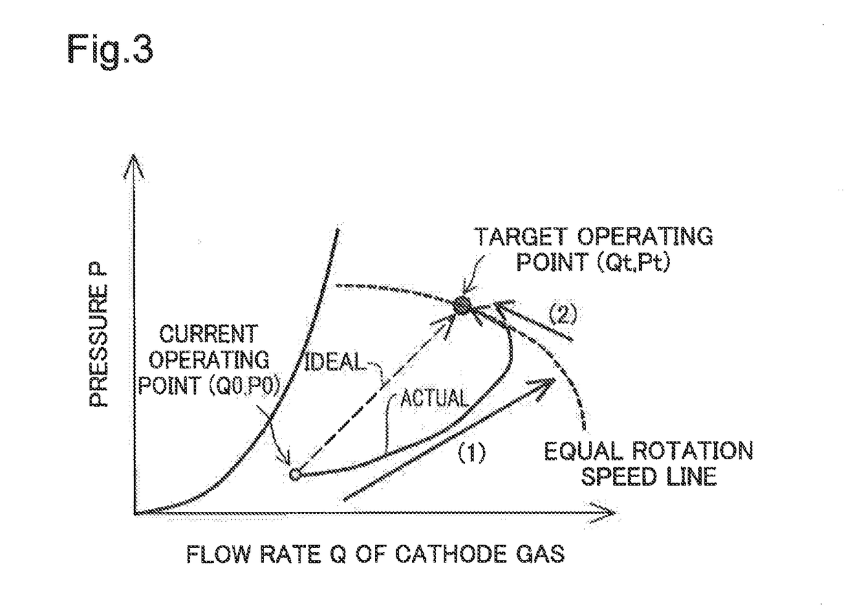
CROSS-REFERENCE TO RELATED APPLICATIONS[0001]The present application claims priority from Japanese patent application 2016-46401 filed on Mar. 10, 2016, the content of which is hereby incorporated by reference into this application.BACKGROUND[0002]Field[0003]The present disclosure relates to a fuel cell system and a control method of the same.[0004]Related Art[0005]JP 2004-355890A describes a fuel cell system configured to adjust a supply amount of a cathode gas that is to be supplied to a fuel cell stack, using a rotation speed of a compressor and an opening position of a pressure regulation valve of the cathode gas. In order to suppress an overshoot of the flow rate of the cathode gas, this fuel cell system calculates a response correction amount of the rotation speed of the compressor and adjusts the supply amount of the cathode gas.[0006]When the compressor used is a turbo-type compressor, however, the flow rate significantly changes with a change of the pressure even at a fixed...

Claims


Application Information

Patent Timeline
IPC IPC(8): H01M8/04746H01M8/0432H01M8/04111H01M8/04537H01M8/04992H01M8/02
CPCH01M8/04753H01M8/04992H01M8/04358H01M8/04111H01M8/04649H01M8/02H01M8/04395H01M8/0494Y02E60/50
Inventor IIO, ATSUOYAMANAKA, TOMIOODA, KOHEISUGIYAMA, NAOKI
Owner TOYOTA JIDOSHA KK
Learn More