Eureka AIR delivers breakthrough ideas for toughest innovation challenges, trusted by R&D personnel around the world.

Permanent magnet synchronous motor current increment prediction algorithm

A permanent magnet synchronous motor, current increment technology, applied in the control of generators, motor generator control, control of electromechanical brakes, etc., can solve problems such as a large amount of calculation

Active Publication Date: 2014-01-15
TSINGHUA UNIV
View PDF6 Cites 22 Cited by
  • Summary
  • Abstract
  • Description
  • Claims
  • Application Information

AI Technical Summary

Problems solved by technology

However, the realization of the prediction usually requires the use of precise mathematical models and parameters of the motor, and generally requires a large amount of calculation
In practical applications, it is often difficult to achieve

Method used


Image

  • Permanent magnet synchronous motor current increment prediction algorithm
  • Permanent magnet synchronous motor current increment prediction algorithm
  • Permanent magnet synchronous motor current increment prediction algorithm

Examples


Embodiment Construction

[0031] The present invention will be described in detail below in conjunction with the accompanying drawings and embodiments.

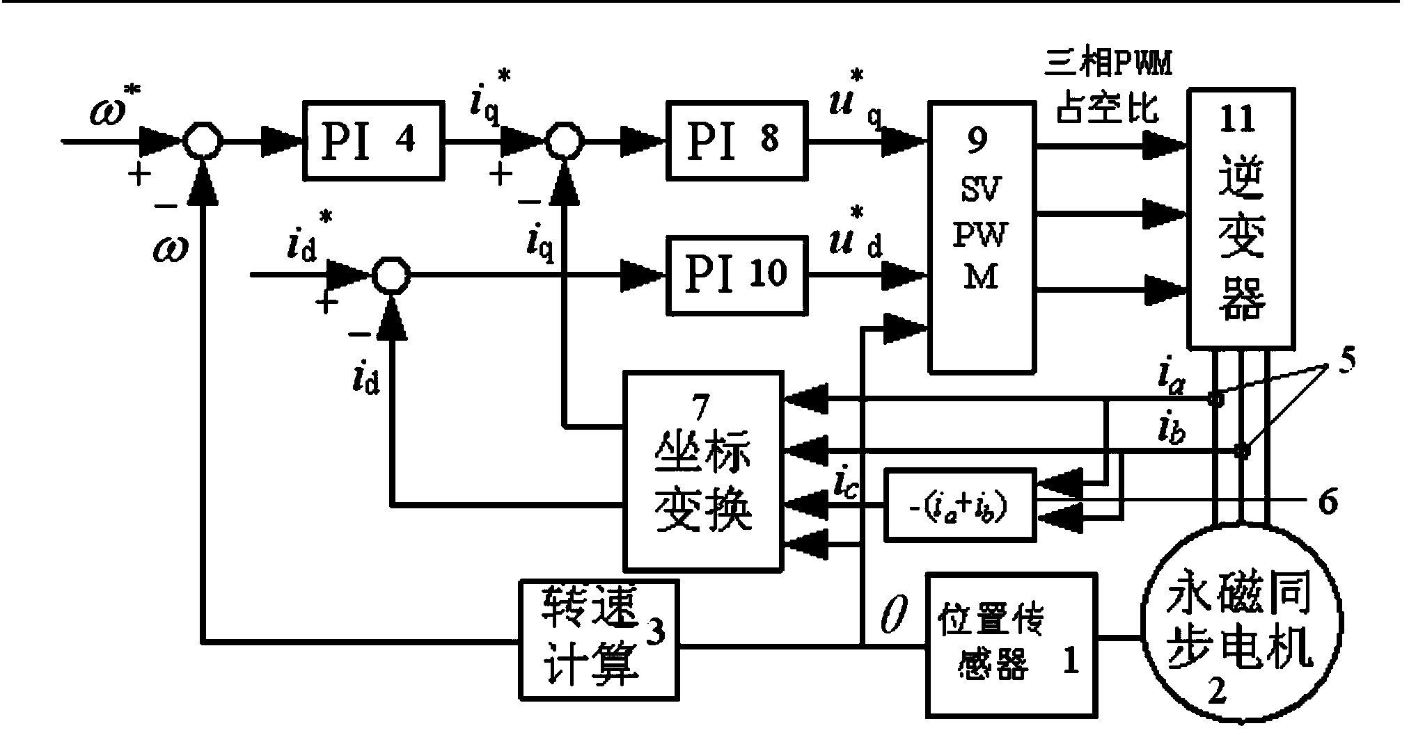
[0032] Such as figure 1 As shown, the present invention takes the permanent magnet synchronous motor vector control system as an example. The permanent magnet synchronous motor vector control system includes a position sensor 1, a permanent magnet synchronous motor (PMSM) 2, a speed calculation module 3, a speed loop PI regulator 4, a current Sensor 5 , summation module 6 , coordinate transformation module 7 , current loop PI regulator 8 , space vector pulse width modulation (SVPWM) module 9 , current loop PI regulator 10 and inverter 11 . Among them, the position sensor 1, the speed calculation module 3 and the speed loop PI regulator 4 form a speed loop; the coordinate transformation module 7 and the current loop PI regulator 8 form a q-axis current loop; the coordinate transformation module 7 and the current loop PI regulator 10 form a The d-axis ...


PUM


Abstract

The invention relates to a permanent magnet synchronous motor current increment prediction algorithm which comprises the following steps: (1) a stator d shaft voltage equation and a stator q shaft voltage equation of a permanent magnet synchronous motor in a synchronous rotating reference frame are established; (2) according to the stator q shaft voltage equation in the step (1), discrete voltage equations of the permanent magnet synchronous motor are established in the current period and the previous period respectively; (3) changes in voltage items relevant to rotating speed are ignored, and the discrete voltage equations of the permanent magnet synchronous motor are subtracted to obtain a current increment formula of the permanent magnet synchronous motor; (4) a pulse transfer function between a current predicted value and a current detected value in the current period is obtained according to a transfer function of the permanent magnet synchronous motor and the current increment formula of the permanent magnet synchronous motor; (5) a closed loop pulse transfer function of a q shaft current loop by means of the current increment prediction algorithm is obtained according to the pulse transfer function, a pulse transfer function of a traditional current loop PI regulator, and the transfer function of the permanent magnet synchronous motor. The permanent magnet synchronous motor current increment prediction algorithm can be widely applied to the field of permanent magnet synchronous motor servo control.

Description

technical field [0001] The invention relates to the field of servo control of permanent magnet synchronous motors, in particular to a current increment prediction algorithm of permanent magnet synchronous motors. Background technique [0002] With the continuous improvement and improvement of the performance of permanent magnet materials and the gradual maturity of the research and development experience of permanent magnet motors, permanent magnet synchronous motors are developing towards high power, high performance and miniaturization. Due to the use of permanent magnets to provide air-gap flux, permanent magnet synchronous motors have the advantages of simple structure, small size, light weight, low loss, and high efficiency, and have been widely used in high-performance servo control and other fields. High-performance servo applications generally require fast electromagnetic torque response to ensure high dynamic performance of the entire system. Increasing the choppin...

Claims


Application Information

Patent Timeline
IPC IPC(8): H02P21/14
Inventor 肖曦王伟华丁有爽
Owner TSINGHUA UNIV
Why Eureka
Eureka Blog
Learn More