Method and apparatus for x-ray microscopy

a microscopy and x-ray technology, applied in the field of microscopy systems using x-rays, can solve the problems of limited resolution, system limited field of view, and general limitations of conventional x-ray microscopes that utilize imaging optics, and achieve the effect of enhancing detection efficiency and pixel siz

Active Publication Date: 2017-09-14
SIGRAY INC
View PDF2 Cites 37 Cited by
  • Summary
  • Abstract
  • Description
  • Claims
  • Application Information

AI Technical Summary

Benefits of technology

This patent describes a method for creating high-resolution images of microscopic objects using a special setup. The method involves placing the detector and the object within the same range of a set of Talbot anti-nodes, either by moving the object or by adjusting a detector mount. This allows for the creation of a scanned transmission image or a laminographic or tomographic image reconstruction using data collected from the micro-beams. The use of additional masking layers can improve the efficiency and accuracy of the detector, and these layers can be placed in front of the object or integrated into the detector structure. Overall, this method allows for the creation of high-quality images of microscopy samples using advanced technology.

Problems solved by technology

Conventional x-ray microscopes that utilize imaging optics are generally limited by the resolution of the x-ray optics (e.g. zone plates) and / or the resolution of the pixel size of the detector.
For projection-based systems, the resolution is limited by the size of the x-ray source and the finite pixel size of the detector.
Although some commercial x-ray microscope systems utilizing zone plates have a resolution of less than 100 nm, such systems have an extremely limited field of view.
Projection based x-ray microscopes do provide reasonable field of view with resolution better than 1 micron, but the acquisition times for reasonable signal-to-noise ratio tend to be very long, rendering the technique practically useless for many applications.
Therefore, x-ray microscopy with resolution smaller than 1 micron while also having a large field-of-view has difficulty producing images with an integration time short enough to make the technique practical.

Method used


Image

  • Method and apparatus for x-ray microscopy
  • Method and apparatus for x-ray microscopy
  • Method and apparatus for x-ray microscopy

Examples


Embodiment Construction

[0034]1. Imaging with Arrays of Micro-Beams.

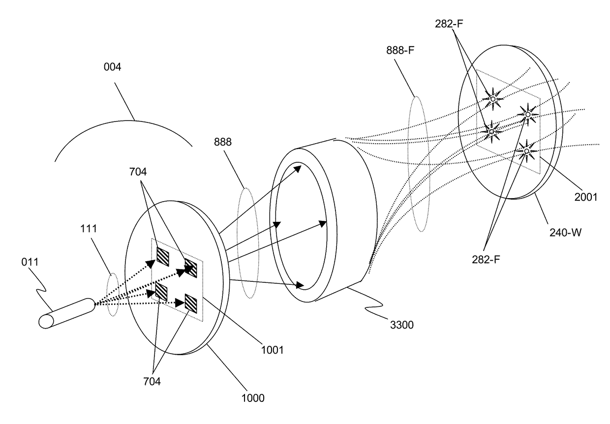
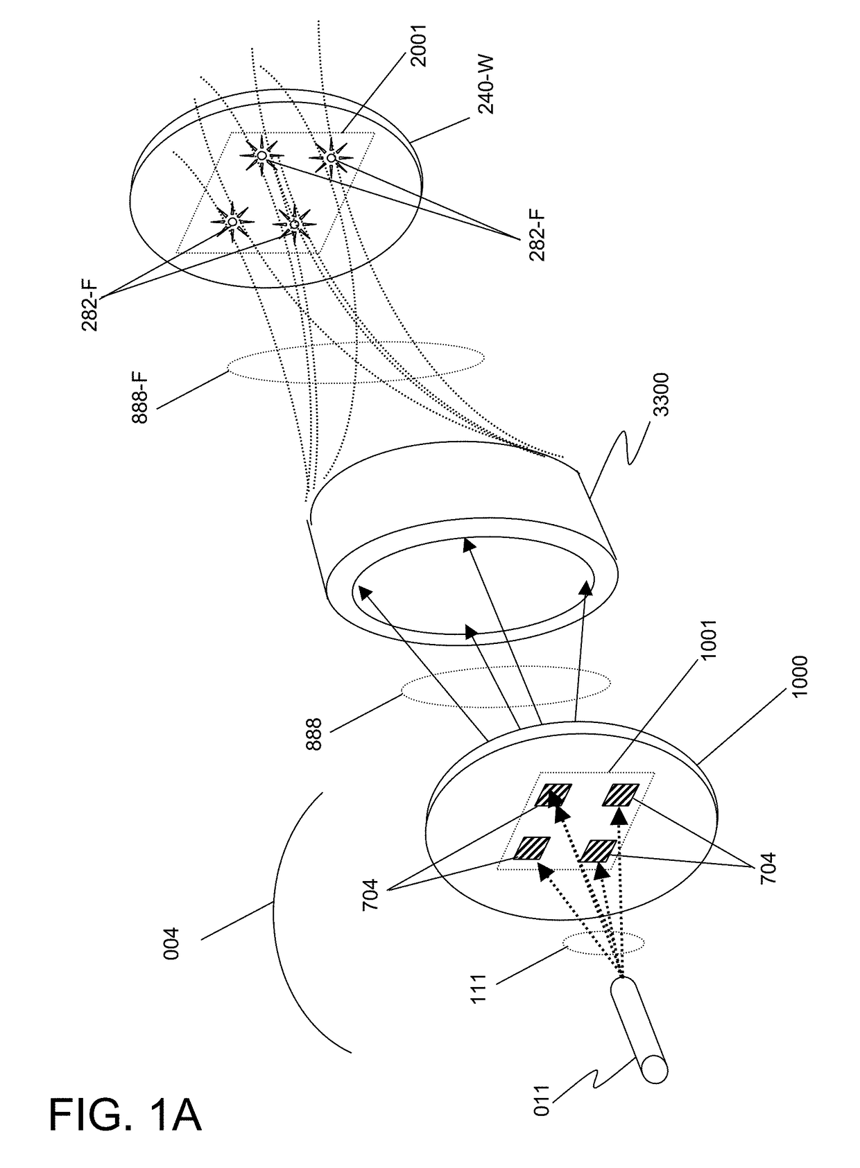
[0035]FIG. 1A illustrates a simple embodiment of the invention comprising the formation of an array of micro-beams. An arrayed source 004 comprising an electron emitter 011 that produces electrons 111 that bombard a target 1000 comprising a region 1001 containing structures of x-ray generating materials 704. In this illustration, four material structures 704 that are sub-sources of the x-rays are shown arranged in an array, although the target may comprise any number of source points and, of these source points, any number may be used.

[0036]The four structures of x-ray generating materials 704, when bombarded by electrons 111, produce x-rays 888 that propagate away from the target. In the embodiment as illustrated, these x-rays 888 enter an x-ray optical system 3300 that converts the waveform into focused x-rays 888-F that form an image of the x-ray array region 1001 at a predetermined region 2001 in space. Such an optical system may be a ...


PUM


Abstract

This disclosure presents systems for x-ray microscopy using an array of micro-beams having a micro- or nano-scale beam intensity profile to provide selective illumination of micro- or nano-scale regions of an object. An array detector is positioned such that each pixel of the detector only detects x-rays corresponding to a single micro- or nano-beam. This allows the signal arising from each x-ray detector pixel to be identified with the specific, limited micro- or nano-scale region illuminated, allowing sampled transmission image of the object at a micro- or nano-scale to be generated while using a detector with pixels having a larger size and scale. Detectors with higher quantum efficiency may therefore be used, since the lateral resolution is provided solely by the dimensions of the micro- or nano-beams. The micro- or nano-scale beams may be generated using an arrayed x-ray source or a set of Talbot interference fringes.

Description

CROSS-REFERENCE TO RELATED APPLICATIONS[0001]This Patent Application is a continuation-in-part of U.S. patent application Ser. No. 15 / 173,711, filed Jun. 5, 2016 and entitled “X-RAY TECHNIQUES USING STRUCTURED ILLUMINATION”, which claims the benefit of U.S. Provisional Patent Application Nos. 62 / 171,377, filed on Jun. 5, 2015 and entitled “X-RAY TECHNIQUES USING STRUCTURED ILLUMINATION”, and 62 / 343,594, filed on May 31, 2016 and entitled “X-RAY MICRODIFFRACTION WITH STRUCTURED ILLUMINATION FOR STRAIN MEASUREMENT IN NANOELECTRONICS”, all of which are incorporated herein by reference in their entirety.application Ser. No. 15 / 173,711 additionally is a continuation-in-part of U.S. patent application Ser. No. 14 / 712,917, filed May 15, 2015 and entitled “X-RAY METHOD FOR MEASUREMENT, CHARACTERIZATION, AND ANALYSIS OF PERIODIC STRUCTURES”, which in turn is a continuation-in-part of U.S. patent application Ser. No. 14 / 700,137, filed Apr. 29, 2015 and entitled “X-RAY INTERFEROMETRIC IMAGING ...

Claims


Application Information

Patent Timeline
IPC IPC(8): G01N23/04G21K1/06G21K7/00G01N23/20
CPCG01N23/04G01N23/20075G01N2223/313G21K7/00G01N2223/3306G21K1/067A61B6/4007A61B6/4291A61B6/484A61B6/508G01N23/201G21K1/02G21K2207/005H01J2235/086H01J2235/1291H01J35/116
Inventor YUN, WENBINGLEWIS, SYLVIA JIA YUNKIRZ, JANOSSESHADRI, SRIVATSANLYON, ALAN FRANCISREYNOLDS, DAVID CHARLES
Owner SIGRAY INC
Why Eureka
Try Eureka