
Abrasive-fluid jet cutting device

Active Publication Date: 2017-09-14
C M S COSTRUZIONE MACCHINE SPECIALI
View PDF2 Cites 4 Cited by
  • Summary
  • Abstract
  • Description
  • Claims
  • Application Information

AI Technical Summary

Benefits of technology

The fluid jet cutting device described in this patent has several advantages. Firstly, it can keep the particles (abrasive) dry along part of the path they are mixed with the fluid. Secondly, it can prevent the humidity from coming back along the path of the particles. Thirdly, it reduces the risk of problems with the supply flow of the particles. Fourthly, it is very small in size. Fifthly, it allows the particles to slide easily and regularly into the mixing area with the fluid. Lastly, it is easy to make and inexpensive.

Problems solved by technology

Prior-art abrasive fluid jet cutting devices are improvable in several ways.

Method used


Image

  • Abrasive-fluid jet cutting device
  • Abrasive-fluid jet cutting device
  • Abrasive-fluid jet cutting device

Examples


Embodiment Construction

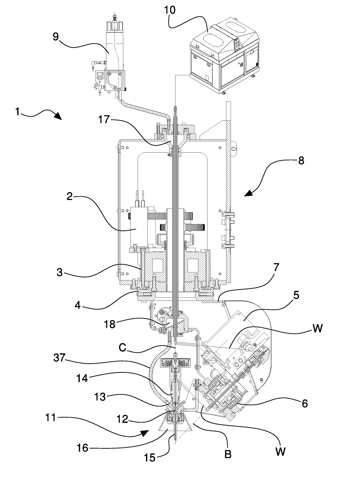
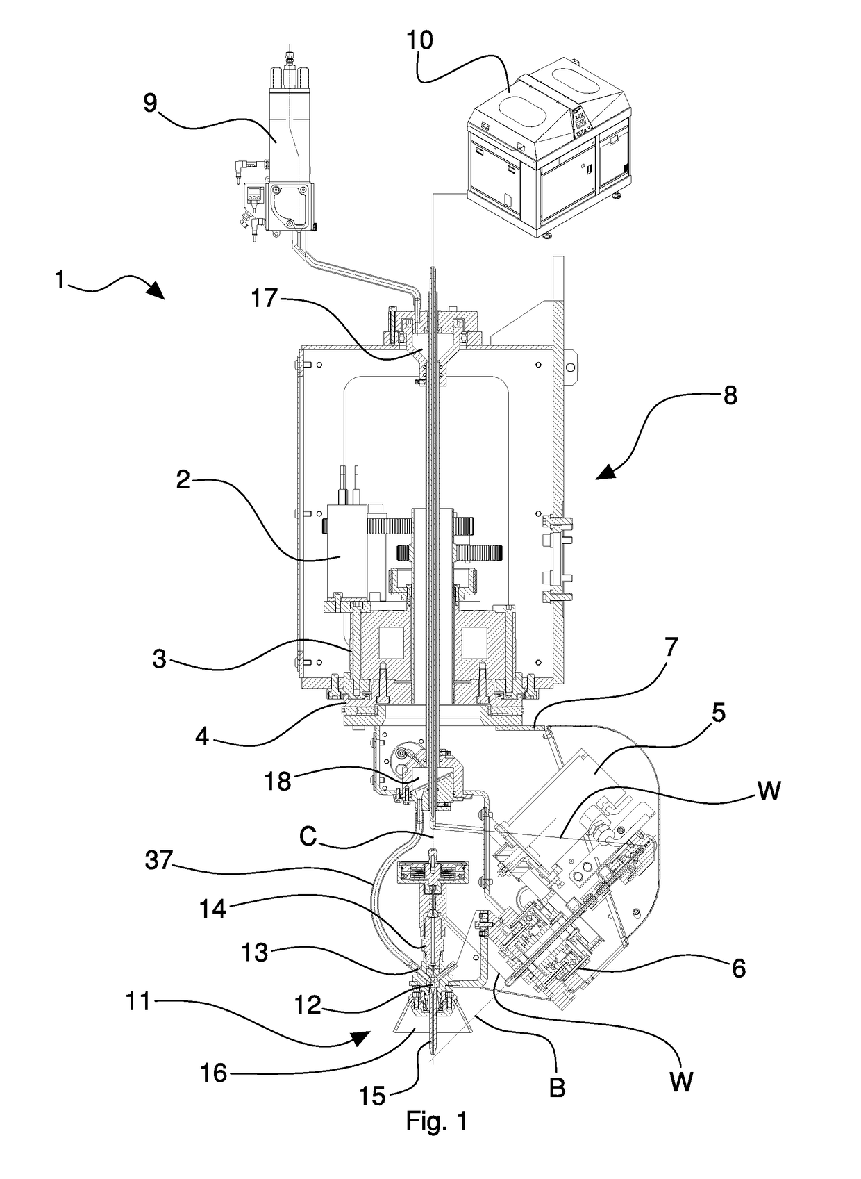
[0019]With reference to the aforesaid figures, with 1 overall a fluid jet cutting device (water) with solid particles (abrasive) has been indicated. In particular, the cutting device 1 can be arranged on a machining center (not shown, for example of known type), for example a machining center with five controlled axes. The cutting device 1 can be, for example, movable on three orthogonal reciprocally linear axes X, Y, Z (not shown). The cutting device 1 can be, further, movable on two rotation axes C and B (as will be explained better below). The cutting device 1 can be used, for example, to cut objects made of stone, marble, granite, glass, metal, and any material that is suitable for machining with abrasive water jet technology.

[0020]The cutting device 1 is movable around a C axis (usually called the fourth axis). The C axis comprises a vertical rotation axis.

[0021]The cutting device 1 is movable around a B axis (usually known as the fifth axis). The B axis comprises an oblique ro...


PUM

PropertyMeasurementUnit
Timeaaaaaaaaaa
Volumeaaaaaaaaaa
Shapeaaaaaaaaaa

Abstract

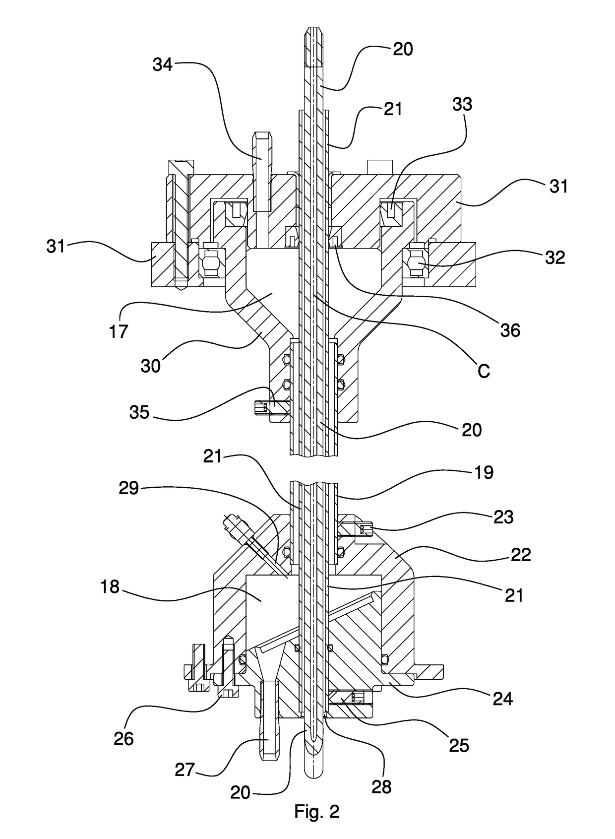
An abrasive fluid jet cutting device is disclosed comprising a rotating joint that includes a first path for abrasive and a second path for fluid, a mixing chamber where the first and second paths meet, a first expanding volume arranged above the first path to accumulate abrasive, and a second expanding volume arranged below the first path to accumulate abrasive between the first volume and the mixing chamber, in which the second volume forms a barrier against the return flow of humidity along the first path.

Description

BACKGROUND OF THE INVENTION[0001]The invention relates to a cutting device for making cuts with a jet of a mixture of fluid (in general water) and solid particles (abrasive).[0002]Specifically, but not exclusively, the invention can be usefully used in a numerically controlled machining center, for example with five controlled axes.[0003]Patent publication U.S. Pat. No. 4,854,091 shows an abrasive fluid jet cutting machine with a rotating assembly that defines a mixing chamber in which the abrasive is introduced into a flow of pressurised water.[0004]Patent publication U.S. Pat. No. 8,425,280 shows an abrasive fluid jet cutting machine in which a rotating distributor has a stator and a rotor between which there is a cavity with a tilted bottom to convey the particles of abrasive to an outlet and thus to the mixing chamber.[0005]Patent publication U.S. Pat. No. 8.540,552 shows an abrasive fluid jet cutting machine in which high-pressure water flows along a first passage in a rotating...

Claims


Application Information

Patent Timeline
IPC IPC(8): B24C7/00
CPCB24C7/003B24C1/045B24C5/02B24C7/00B24C7/0076
Inventor ORLANDI, DAVIDEBENAGLIA, STEFANOPEDRINI, GIUSEPPE
Owner C M S COSTRUZIONE MACCHINE SPECIALI
Learn More