
Electronic circuit for single-event latch-up detection and protection

a technology of electronic circuits and latches, applied in the direction of electrical equipment, basic electric elements, automatic disconnection emergency protection arrangements, etc., can solve the problem and achieve the effect of rapid increase in current change ra

Active Publication Date: 2017-08-17
ZERO ERROR SYST PTE LTD
View PDF3 Cites 6 Cited by
  • Summary
  • Abstract
  • Description
  • Claims
  • Application Information

AI Technical Summary

Benefits of technology

The patent discusses a method for detecting a specific event called an SEL, which can cause a rapid increase in load current. By measuring the rate at which the load current changes, the method allows for detection of the SEL event sooner than if the absolute load current value were used alone. This results in quicker and more accurate detection of the SEL event, which can help to prevent damage or other negative effects.

Problems solved by technology

This is because a SEL event is likely to result in a rapid increase in the current change rate even before an absolute load current threshold is reached.

Method used


Image

  • Electronic circuit for single-event latch-up detection and protection
  • Electronic circuit for single-event latch-up detection and protection
  • Electronic circuit for single-event latch-up detection and protection

Examples


first embodiment

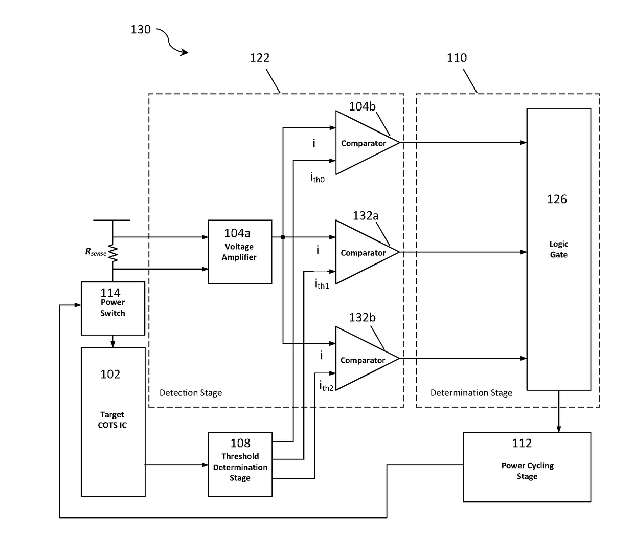
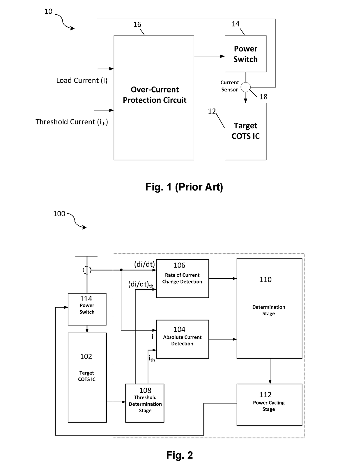
[0042]In accordance with the present invention there is provided an electronic circuit 100 for single-event latch-up (SEL) detection and protection as shown in FIG. 2. The circuit 100 comprises a target COTS IC 102 coupled to a first detector 104 for detecting the absolute load current (i) of the IC 102 and a second detector 106 for detecting the rate of change of load current (di / dt) for the IC 102. Together, the first and second detectors 104, 106 can be considered to constitute a detection stage as will be explained in more detail below.

[0043]A threshold determination unit 108 is provided between the IC 102 and each of the first detector 104 and second detector 106 for providing a threshold current (ith) and threshold current change rate (di / dt)th. In this embodiment, the threshold current (ith) and threshold current change rate (di / dt)th are pre-programmed into the threshold determination unit 108. However, in other embodiments the threshold values may be determined by monitorin...

second embodiment

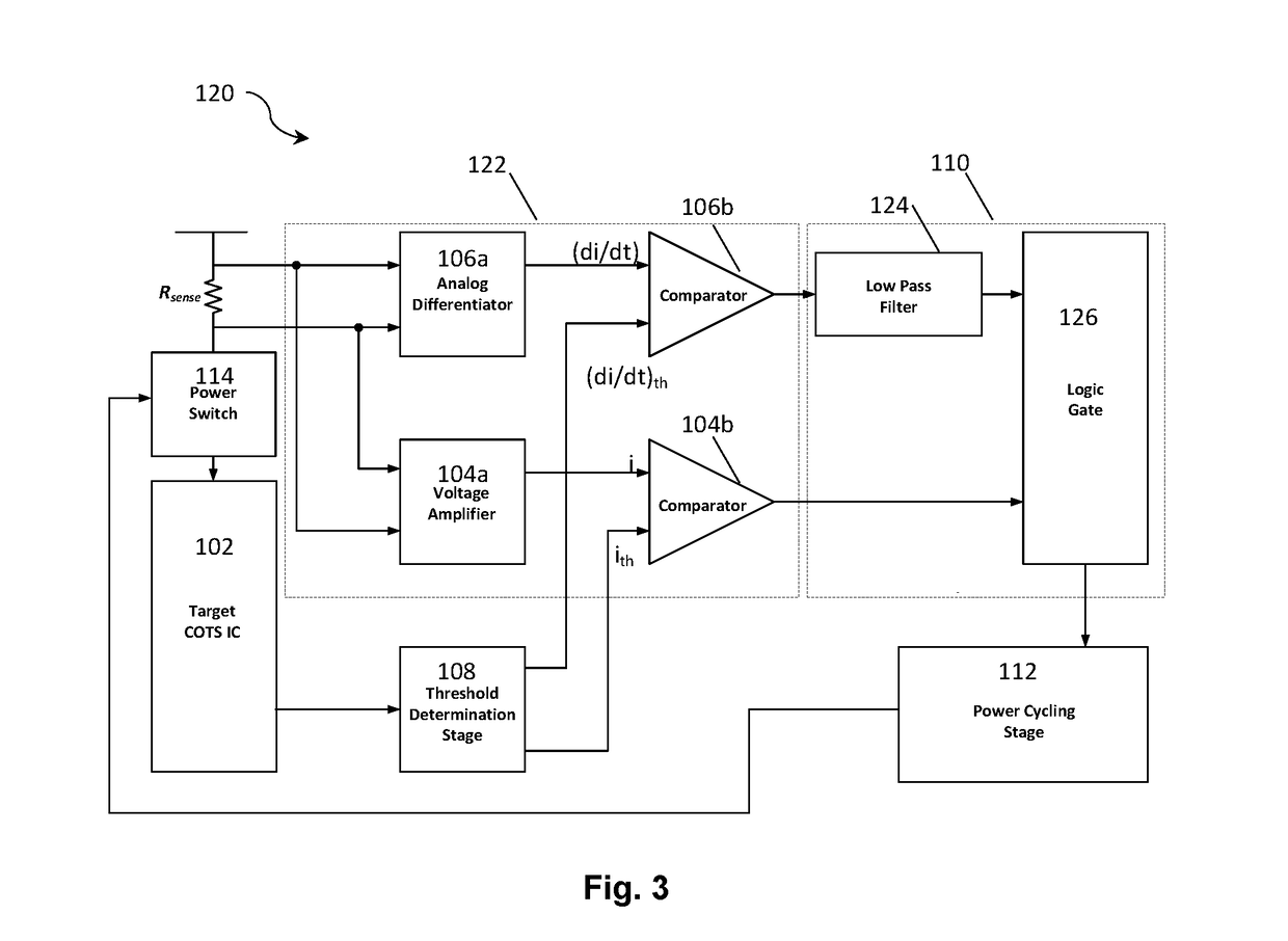
[0056]Table 1 tabulates the response time and shut-down current for the present invention described above in relation to FIG. 3 and the conventional approach, when an SEL event is detected. At 150 mA nominal load current, the embodiment of the invention is able to identify the SEL occurrence and shut down the power supply within 100 μs. This is a significant 7.5 times faster than the conventional approach. Furthermore, the shutdown current (i.e. load current when the SEL detection and protection circuit is triggered) is a low 180 mA (which is equivalent to 1.2 times the nominal current) when using the embodiment of the invention. This is a significant greater than 2 times lower than the conventional approach. Thus, embodiments of the invention can achieve a substantially lower shutdown current and a substantially faster response time than the current state of the art. This translates to substantially-enhanced SEL protection for a target IC, and hence the lifetime of a COTS IC can be...


PUM


Abstract

An electronic circuit for single-event latch-up (SEL) detection and protection of a target integrated circuit (IC) is disclosed. The circuit comprises: a first detector configured for detecting an absolute load current (i) and comparing the absolute load current (i) with a threshold current (ith); a second detector configured for detecting a rate of change of load current (di / dt) and comparing the rate of change of load current (di / dt) with a threshold current change rate (di / dt)th; and a determination module for triggering a power shut-down to the target IC if the absolute load current (i) exceeds the threshold current (ith) and / or the rate of change of load current (di / dt) exceeds the threshold current change rate (di / dt)th.

Description

FIELD OF THE INVENTION[0001]The present invention relates to an electronic circuit for single-event latch-up (SEL) detection and protection. Particularly, but not exclusively, the invention relates to such a circuit that is suitable for use in space applications.BACKGROUND[0002]There is great interest and demand to adopt Complementary Metal-Oxide Semiconductor (CMOS) Commercial-Off-The-Shelf (COTS) Integrated Circuits (ICs) instead of space-grade ICs in space applications, largely due to their higher performance (including functionalities), lower cost and availability. It is also well-known that COTS ICs are subjective to various radiation effects including the accumulative effect of Total Ionizing Dose (TID) and a number of single-event effects such as those described as Single Event Transient (SET), Single Event Upset (SEU) and Single Event Latch-up (SEL), etc. Amongst said radiation effects, SEL is the most devastating because, unlike other effects that largely introduce errors o...

Claims


Application Information

Patent Timeline
IPC IPC(8): H02H3/10H02H1/00
CPCH02H1/0007H02H3/10H02H3/08H02H3/44H01L27/0248H02H5/005
Inventor CHANG, JOSEPH SYLVESTERSHU, WEIJIANG, JIZE
Owner ZERO ERROR SYST PTE LTD
Learn More