Pressure detection unit and pressure sensor using the same
a technology of pressure detection unit and pressure sensor, applied in the field of pressure sensors, can solve problems such as defect generation, and achieve the effect of suppressing weight increase and suppressing detection accuracy
- Summary
- Abstract
- Description
- Claims
- Application Information
AI Technical Summary
Benefits of technology
Problems solved by technology
Method used
Image

Examples
embodiment 1
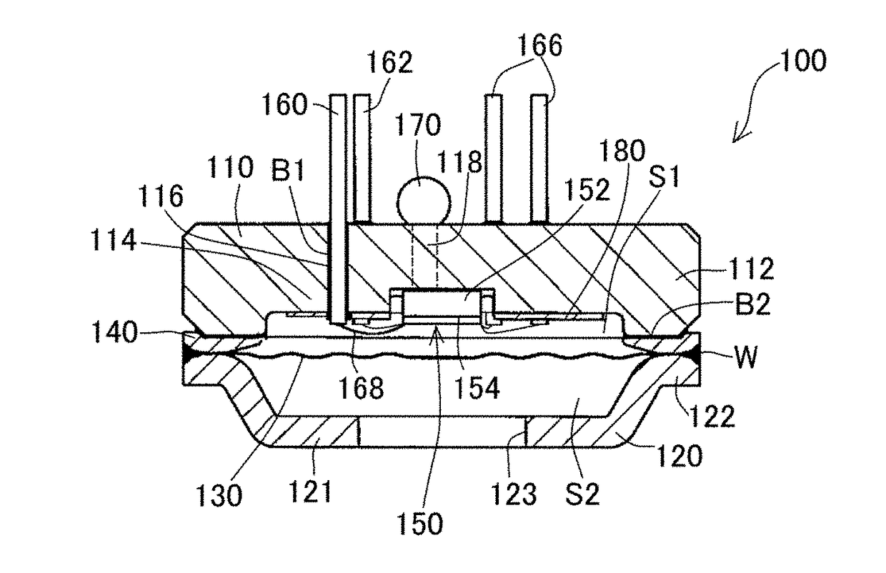
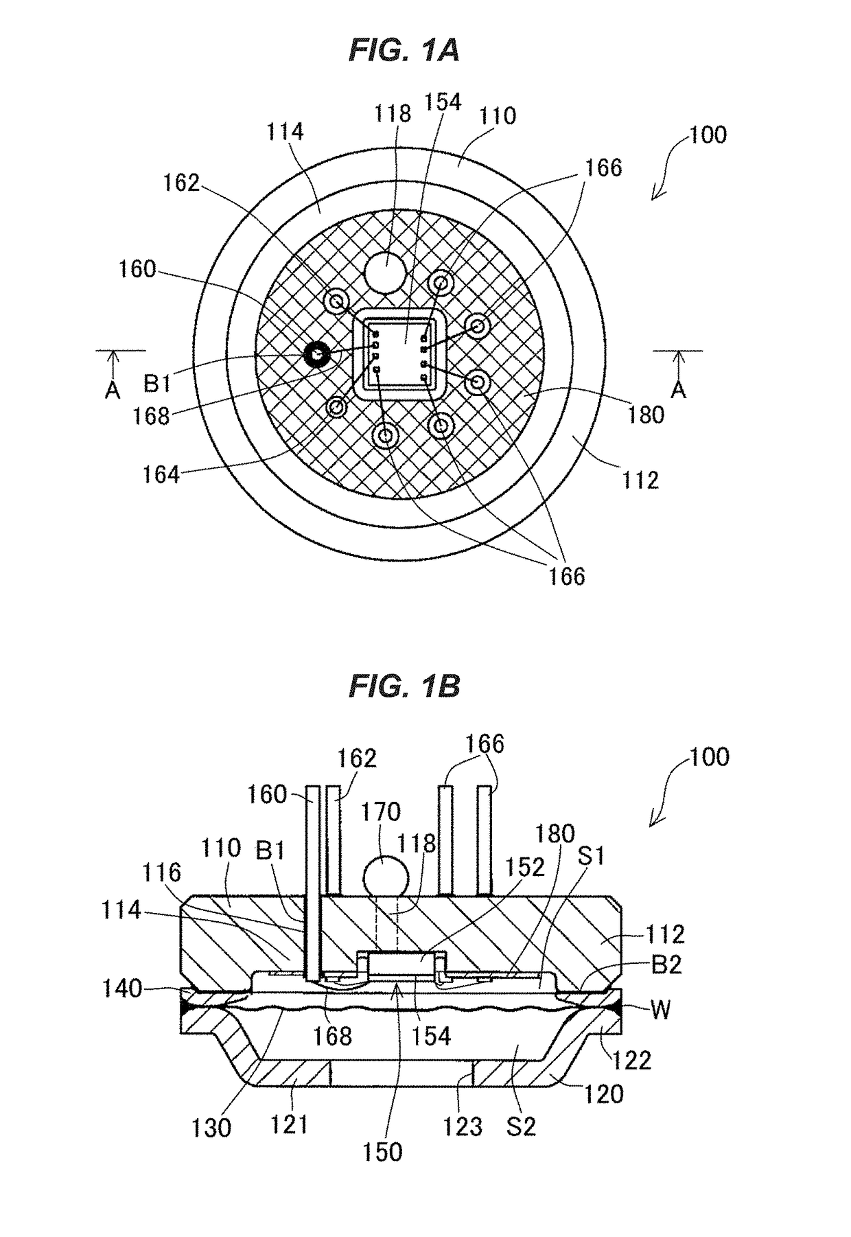
[0026]FIGS. 1 A and 1B depict an outline of a pressure detection unit according to Embodiment 1 of the invention. FIG. 1A illustrates a top view of the pressure detection unit, and FIG. 1B illustrates a cross section taken along A-A line of FIG. 1A in side view.
[0027]As illustrated in FIG. 1A, the pressure detection unit 100 according to Embodiment 1 of the invention includes a base 110 made of ceramic, a receiving member 120 facing the base 110, and a diaphragm 130 and a ring member 140 interposed between the base 110 and the receiving member 120.
[0028]The base 110 is a circular lid-shaped member in top view, and includes a ceramic material having an insulating property in which an outer circumferential portion 112 and an inner portion 114 having a smaller thickness than that of the outer circumferential portion 112 are integrated with each other as illustrated in FIG. 1B. That is, the base 110 has a shape in which a central portion thereof is recessed such that a pressure receivin...
embodiment 2
[0089]FIGS. 3A and 3B illustrate an outline of a pressure detection unit according to Embodiment 2 of the invention. FIG. 3A illustrates a top view of the pressure detection unit, and FIG. 3B illustrates a cross section taken along A-A line of FIG. 3A in side view.
[0090]As illustrated in FIGS. 3A and 3B, the pressure detection unit 200 according to Embodiment 2 of the invention includes a base 210 made of ceramic, a receiving member 220 facing the base 210, and a diaphragm 230 and a ring member 240 interposed between the base 210 and the receiving member 220.
[0091]Similarly to Embodiment 1, the base 210 is a circular lid-shaped member in top view, and includes a ceramic material having an insulating property in which an outer circumferential portion 212 and an inner portion 214 having a smaller thickness than that of the outer circumferential portion 212 are integrated with each other as illustrated in FIG. 3B. That is, the base 210 has a shape in which a central portion thereof is ...
embodiment 3
[0137]FIG. 5 is a longitudinal sectional view of a cross section passing through a central line of a pressure detection unit according to Embodiment 3 of the invention when seen from a side view.
[0138]As illustrated in FIG. 5, the pressure detection unit 300 according to Embodiment 3 of the invention includes a base 310 made of ceramic, a receiving member 320 facing the base 310, a diaphragm 330 and a ring member 340 interposed between the base 310 and the receiving member 320, and a caulking member 390 that integrally fixes the base 310 and the receiving member 320 from an outer circumferential side.
[0139]Similarly to Embodiment 1, the base 310 is a circular lid-shaped member in a top view, and includes a ceramic material having an insulating property in which an outer circumferential portion 312 and an inner portion 314 having a smaller thickness than that of the outer circumferential portion 312 are integrated with each other as illustrated in FIG. 5. That is, the base 310 has a ...
PUM
 Abstract
Description
Claims
Application Information
 - R&D
- Intellectual Property
- Life Sciences
- Materials
- Tech Scout
- Unparalleled Data Quality
- Higher Quality Content
- 60% Fewer Hallucinations
Browse by: Latest US Patents, China's latest patents, Technical Efficacy Thesaurus, Application Domain, Technology Topic, Popular Technical Reports.
© 2025 PatSnap. All rights reserved.Legal|Privacy policy|Modern Slavery Act Transparency Statement|Sitemap|About US| Contact US: help@patsnap.com