Guide element for a pressure system of an internal combustion engine, pressure system for an intake tract of an internal combustion engine, and internal combustion engine with a supercharging unit
a pressure system and internal combustion engine technology, applied in the direction of combustion air/fuel air treatment, intake silencers for fuel, machines/engines, etc., can solve the problems of uncontrolled combustion and so-called knocking, and achieve low charge exchange work, low fuel consumption, and low temperature of the cylinder charge
- Summary
- Abstract
- Description
- Claims
- Application Information
AI Technical Summary
Benefits of technology
Problems solved by technology
Method used
Image
Examples
first embodiment
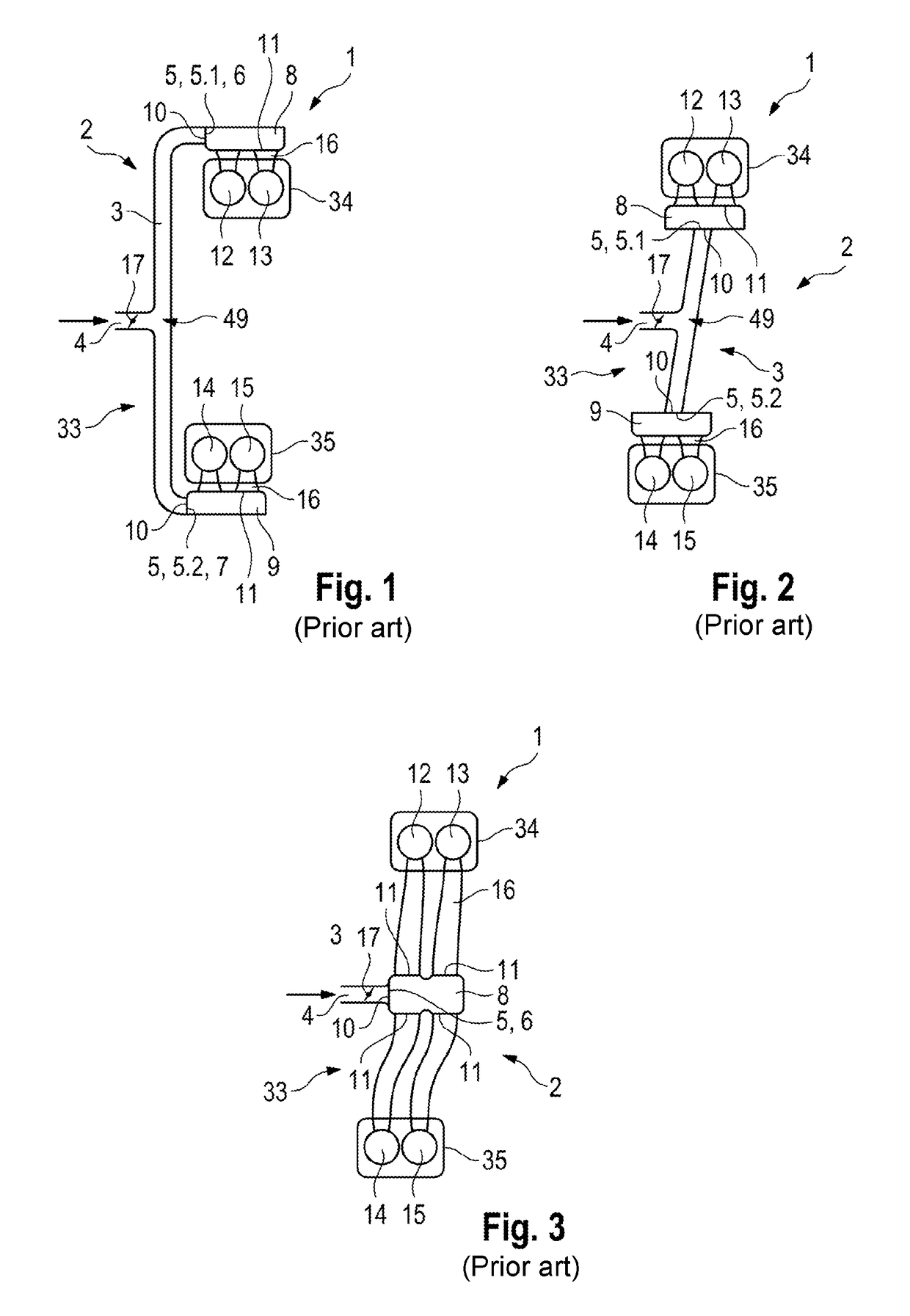
[0062]FIG. 6 shows, in a schematic illustration, an internal combustion engine 1 according to the invention with a pressure system 33 according to the The internal combustion engine 1 is assigned the supercharging unit 18 in the form of the exhaust-gas turbocharger, and a compressor 19 of the exhaust-gas turbocharger 18 is positioned in the intake tract 2 upstream of the throttle flap 17 with a throttle flap diameter DK and a turbine 20 is positioned downstream of the cylinders 12, 13, 14, 15 in the exhaust tract 21 of the internal combustion engine 1. For the cooling of fresh air that is drawn in and compressed by way of the compressor 19, a charge-air cooler 22 is arranged in the intake tract 2 between the throttle flap 17 and the compressor 19. An air filter 23 for filtering the drawn-in fresh air is provided in the intake tract 2 upstream of the compressor 19. It would likewise also be possible for the supercharging unit 18 to be in the form of a mechanical charger, for example...
second embodiment
[0080]The guide element 25 according to the invention is designed according to FIG. 9. The support element 30 is of ring-shape and has, on its element surface 40 formed so as to face towards the guide element outlet 28, a ring-shaped protuberance 41 that is formed to produce a sealed connection to a further support element 42. The further support element 42 is in the form of a pipe flange, and is designed to concentrically receive and surround, the guide element 25. The further support element 42 is formed integrally with the distributor pipe 3 or the first pipe section 3.1. The further support element could also be formed as an individual component configured to achieve a pressure-tight connection to the pipe sections 3.1, 3.2.
[0081]The guide element 25 has its non-streamlined form owing to its element inner contour 43, which is not designed to run flush, or to terminate flush, with a pipe inner contour 44 of the first pipe section 3.1. Since the guide element outlet diameter DD is...
third embodiment
[0085]FIG. 11 illustrates the pressure system 33 according to the invention in a In this embodiment, the collector tanks 8, 9 assigned to in each case one bank 34, 35 are divided into in each case two bank collector tanks, such that each cylinder 12, 13, 14, 15 is assigned a bank collector tank 8.1, 8.2, 9.1, 9.2. The distributor pipe 3 has two flow outlet openings per bank 34, 35, wherein the first bank collector tank 8.1 is assigned the first flow outlet opening 5.1, the second bank collector tank 8.2 is assigned the second flow outlet opening 5.2, the third bank collector tank 8.3 is assigned the third flow outlet opening 5.3, and the fourth bank collector tank 8.4 is assigned the fourth flow outlet opening 5.4.
PUM
 Abstract
Description
Claims
Application Information
 - R&D
- Intellectual Property
- Life Sciences
- Materials
- Tech Scout
- Unparalleled Data Quality
- Higher Quality Content
- 60% Fewer Hallucinations
Browse by: Latest US Patents, China's latest patents, Technical Efficacy Thesaurus, Application Domain, Technology Topic, Popular Technical Reports.
© 2025 PatSnap. All rights reserved.Legal|Privacy policy|Modern Slavery Act Transparency Statement|Sitemap|About US| Contact US: help@patsnap.com


