
Growing System

Inactive Publication Date: 2017-08-17
STERATEC LTD
View PDF2 Cites 17 Cited by
  • Summary
  • Abstract
  • Description
  • Claims
  • Application Information

AI Technical Summary

Benefits of technology

The present invention is a controlled growing environment that can be powered by solar energy and operated in hot climates. The environment is controlled by a radiation control layer which regulates the level of solar radiation that enters the enclosure. The controlled atmosphere allows for independent control of temperature, humidity, and composition of the atmosphere, and the cooling of the environment can be achieved by ventilation of the ventilated cavity. The construction of the outer enclosure is simplified to protect the inner enclosure. The fine mesh prevents the ingress of insects and windblown sand, and the inner enclosure is suspended from a structural frame located inside the ventilated cavity. The network of rooms is connected by corridors which allow for continuous control of the atmosphere. The invention reduces the heating, cooling, and electric demands of the growing room, making it possible to operate it from solar energy.

Problems solved by technology

Despite the advantages of the above described growing room, it may not offer sufficient control of the growing environment when the growing room is located in extremely hot locations or extremely bright locations.
In the Middle East, for example, where there is substantial incident solar radiation on the growing room, too much heat and / or light may enter the growing room, adversely affecting the produce.
Furthermore, the above described growing room may not be robust enough to survive for a long period of time (twenty years) in a desert environment with high insolation, high UV, high relative humidity, sandstorms, flash flooding and high winds with low maintenance.

Method used


Image

  • Growing System
  • Growing System
  • Growing System

Examples


Embodiment Construction

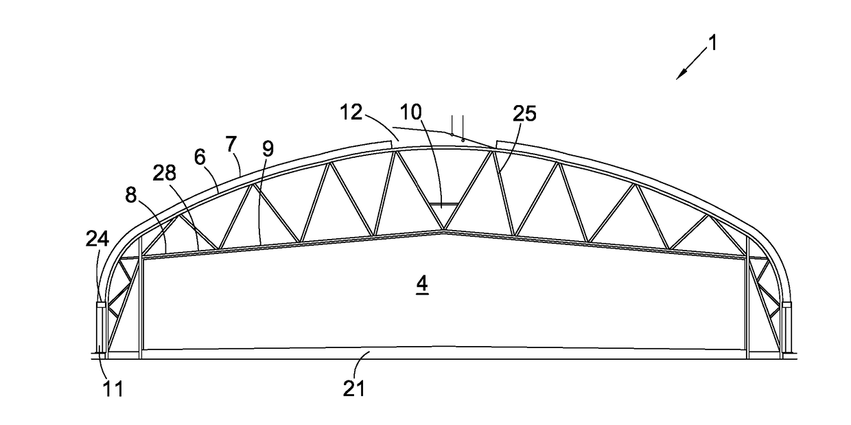
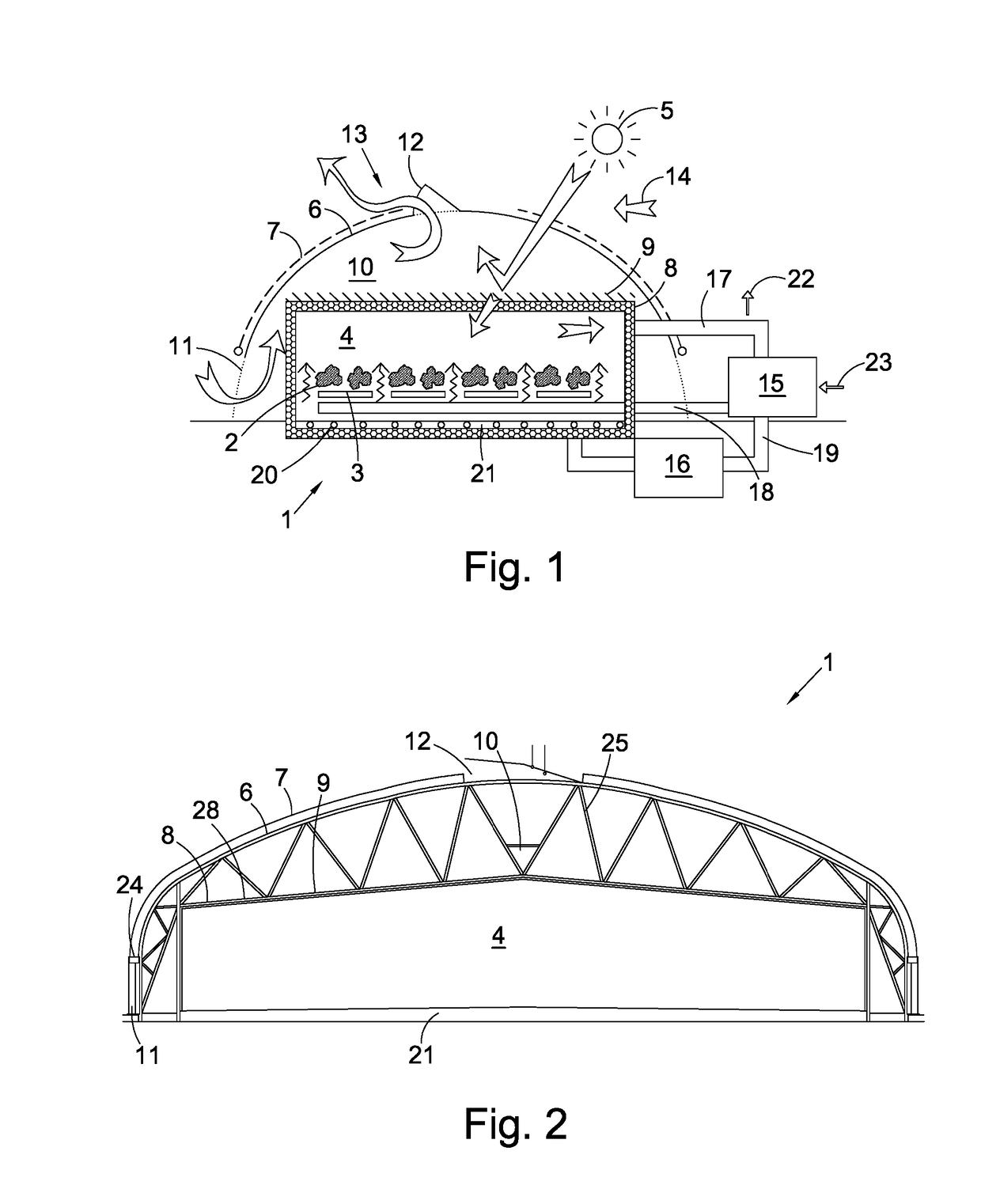
[0037]FIG. 1 shows a diagrammatic view of a growing room 1 according to one embodiment of the present invention. The growing room 1 can be used to grow all manner of produce. Ideally, the produce 2 is grown using Nutrient Film Technique (NFT), provided in gutters 3 beneath the produce. It is also be possible to grow produce using other techniques known to the commercial horticulturalist in a controlled growing environment 4 provided by the growing room 1.

[0038]Electromagnetic radiation from the sun 5 penetrates an outer enclosure 6 which is provided with an outer variable shading system 7 on the exterior surface thereof. The outer enclosure has a sloping roof and is light-transmissive.

[0039]A portion of the electromagnetic radiation penetrating the outer enclosure 6 also penetrates the inner enclosure 8. The inner enclosure is thermally insulated and light-transmissive. An inner variable shading system 9 is provided on the outer surface of the inner enclosure.

[0040]The region betwee...


PUM


Abstract

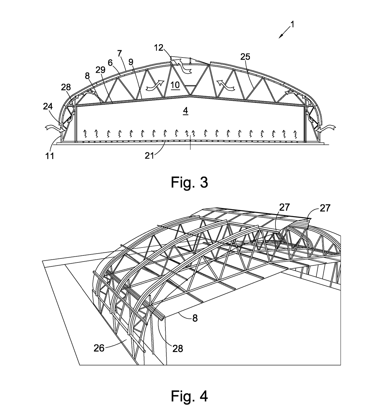
A growing room for providing a controlled growing environment comprises a thermally insulated, light-transmissive inner enclosure (8) for containing the controlled growing environment (4). The inner enclosure 8 encloses, in use, a controlled atmosphere for the controlled growing environment (4). A light-transmissive outer enclosure 6 surrounds the inner enclosure (8) and is arranged to protect the inner enclosure (8) from the external environment, in use. A ventilated cavity (10) is defined between the out er enclosure (6) and inner enclosure (8). The outer enclosure (6) has at least one lower ventilation opening (11) and at least one upper ventilation opening (12) for allowing controlled ventilation of the ventilated cavity (10). A radiation control layer is located in the ventilated cavity (10) between the outer enclosure (6) and the inner enclosure (8) and is arranged to provide controlled absorption of incident solar radiation, whereby to control the level of solar radiation within the controlled growing environment (4).

Description

[0001]This invention relates to a growing system for growing various types of produce in a controlled environment so that the produce is protected from damage by external environmental factors.BACKGROUND[0002]Growing rooms, for example of the type disclosed in EP1439747B1are known. The growing room described therein is designed to enable produce to be grown throughout the year in temperate climate regions, regardless of season and the outside environmental conditions. In temperate conditions, this is achieved by the provision of a room constructed with a double skin structure wherein air from outside can be circulated between the two skin layers to help maintain an evenly distributed temperature throughout the whole growing room. It is advantageous to have the interior of the growing room substantially totally sealed from the outside and this is achieved by allowing access to the growing room only through end rooms attached thereto and by having positive air pressure inside the grow...

Claims


Application Information

Patent Timeline
IPC IPC(8): A01G9/14A01G9/24
CPCA01G9/24A01G9/1415Y02A40/25
Inventor GILLARD, MARTINBURDETT-BROWN, DAVIDDUNSTER, BILL
Owner STERATEC LTD
Learn More