Internal combustion engine

a combustion engine and combustion chamber technology, applied in the direction of machines/engines, valve drives, auxilaries, etc., can solve the problem that the oil mist discharged from the vacuum pump may not be able to be collected, and achieve the effect of large particle diameter and easy collection

Active Publication Date: 2017-07-27
TOYOTA JIDOSHA KK
View PDF2 Cites 3 Cited by
  • Summary
  • Abstract
  • Description
  • Claims
  • Application Information

AI Technical Summary

Benefits of technology

This patent is about an internal combustion engine that collects oil easily. The engine has a structure that allows the oil mist to collide with other oil mist, which increases the particle size of the oil mist and makes it easier to collect. The oil mist and air from the vacuum pump also collide with the oil mist from the oil dispersed by the cam, which promotes liquefaction and makes the oil easier to collect. The engine also has a chain guide located at the bottom of the engine, which has a larger amount of oil than other locations. When the oil mist from the vacuum pump collides with the droplets of oil from the chain guide, the particles of oil get larger, making it easier to collect. Overall, this structure improves the efficiency of collecting oil from the engine.

Problems solved by technology

Therefore, in a related oil separation device, the oil mist discharged from the vacuum pump may not be able to be collected.

Method used


Image

  • Internal combustion engine
  • Internal combustion engine
  • Internal combustion engine

Examples


Embodiment Construction

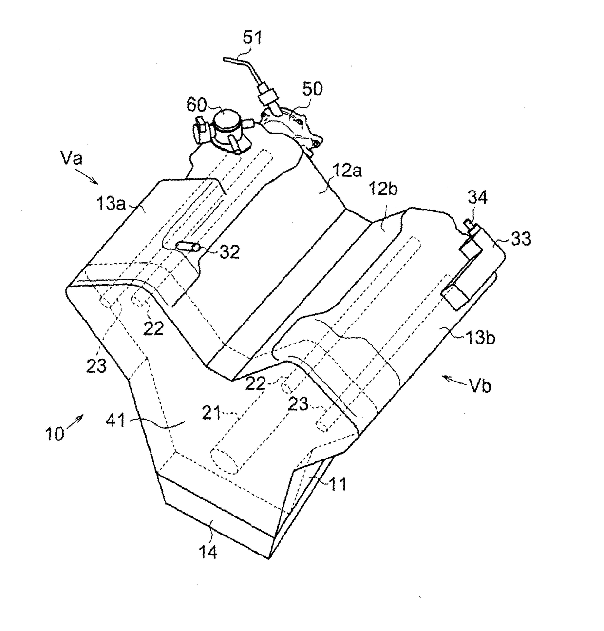
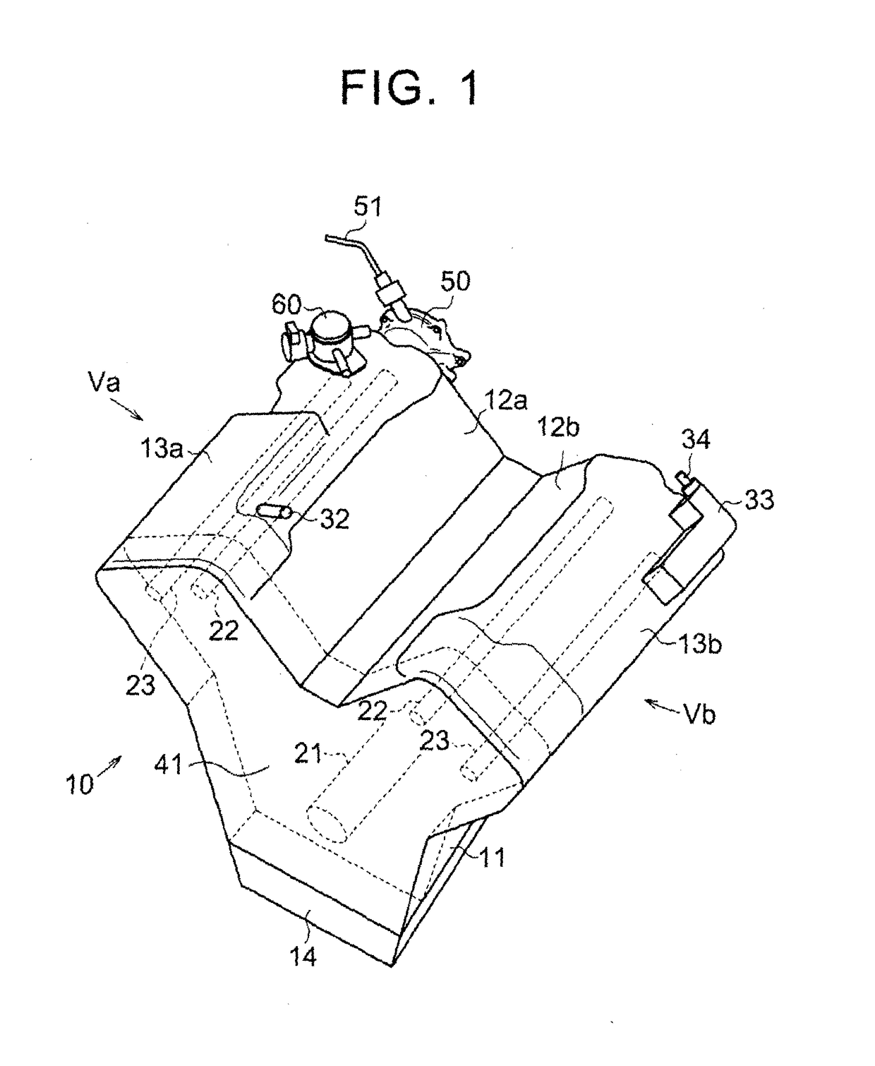
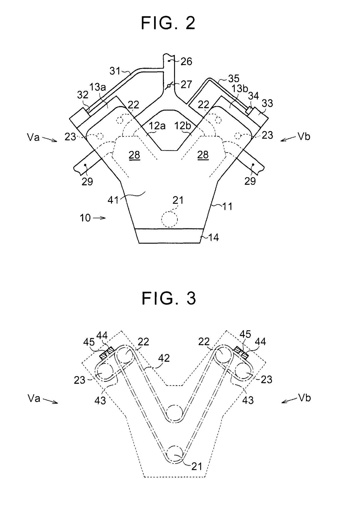
[0024]Hereinafter, one example embodiment of the internal combustion engine of the invention will be described with reference to FIGS. 1 to 7. An internal combustion engine 10 according to this example embodiment is a V-type internal combustion engine with two banks Va and Vb of cylinders. The internal combustion engine 10 includes a crank case 11 that supports a crankshaft 21, a cylinder head 12a that forms the bank Va, and a cylinder head 12b that forms the bank Vb. An oil pan 14 is attached to a lower portion of the crank case 11.

[0025]An intake camshaft 22 that drives an intake valve and an exhaust camshaft 23 that drives an exhaust valve are supported, side by side in parallel, by the cylinder head 12a. Similarly, an intake camshaft 22 and an exhaust camshaft 23 are supported, side by side in parallel, by the cylinder head 12b. That is, each of the banks Va and Vb is provided with an intake camshaft 22 and an exhaust camshaft 23 side by side.

[0026]Also, a head cover 13a is moun...


PUM


Abstract

An internal combustion engine includes a camshaft, a cylinder head, a head cover, a high-pressure pump, and a vacuum pump. The high-pressure pump includes a plunger that abuts against a cam provided on the camshaft. The high-pressure pump is configured to be driven by rotation of the cam such that oil that has lubricated abutting portions of the cam and the plunger collides with an inside wall of the head cover. The vacuum pump is mounted to the cylinder head. The vacuum pump is configured to draw in air from an inlet and discharge an oil mist with air from an outlet. The outlet is arranged such that the oil mist with air from the outlet is discharged into a space where an oil mist formed by a spray of oil that has collided with the inside wall of the head cover stagnates.

Description

BACKGROUND OF THE INVENTION[0001]1. Field of the Invention[0002]The invention relates to an internal combustion engine.[0003]2. Description of Related Art[0004]Japanese Patent Application Publication No. 2012-237234 (JP 2012-237234 A) describes an internal combustion engine provided with a blow-by gas reduction device that includes an oil separation device that separates oil mist from blow-by gas.SUMMARY OF THE INVENTION[0005]An internal combustion engine mounted in a vehicle includes a vacuum pump, and increases brake pedal force using negative pressure generated by drawing in air with this vacuum pump. The vacuum pump draws in air from an inlet and discharges air from an outlet, at which time oil that lubricates the sliding points of the vacuum pump may be discharged together with the air. The oil discharged together with the air from the vacuum pump is injected all at once from the outlet together with air pressurized inside an air chamber of the vacuum pump, and thus becomes a m...

Claims


Application Information

Patent Timeline
Patent Type & Authority Applications(United States)
IPC IPC(8): F01M9/10F02M59/10F02B67/04F01L1/02F01L1/053
CPCF01M9/101F01L1/022F01L1/053F01L2810/02F02M59/10F01L2001/0537F02B67/04F02M59/102F01L1/46F01M13/022F02F1/24F02F7/006
Inventor KUROSAKA, TETSUYA
Owner TOYOTA JIDOSHA KK
Why Eureka
Try Eureka