Fire shield flashing system and method

a flashing system and flashing technology, applied in protective foundations, building components, construction, etc., can solve the problems of lack of outward tilting horizontal legs of steel lintels, staining on the outside surface of outer walls, and weeping open, so as to eliminate or reduce the need for on-site metal fabrication

Active Publication Date: 2017-07-20
YORK MFG
View PDF0 Cites 14 Cited by
  • Summary
  • Abstract
  • Description
  • Claims
  • Application Information

AI Technical Summary

Benefits of technology

[0017]In one test, flame spread for a 78″-wide window opening shall not reach ten feet above the top of the window opening or reach five feet laterally from the window's centerline. Also, thermocouples located in the wall to the sides and above the window opening shall not reach 1000° F. during the test. Builders and teams testing for compliance with NFPA 285 have met these performance requirements by adding components to the wall construction that would not otherwise be present. For example, stainless steel sheet metal is bent to a shallow U-shaped channel and wrapped around the horizontal and vertical edges of the window opening. The stainless steel channels prevent flames from reaching the insulation in the wall cavity. As a result, such an approach reduces heat inside the wall and prevents the insulation from burning. This approach, however, facilitates passing the NFPA 285 test, but it is not consistent with actual construction practices. With no available flashing product designed for fire shielding, a need exists for a fire shield flashing system and method of fenestration flashing for masonry construction.
[0019]Another object of the present invention is to eliminate or reduce the need for on-site metal fabrication machinery and personnel schooled in metal fabrication.
[0020]Yet another object of the present invention is to provide a fenestration flashing system having a finish material that closes the gap between the façade or outer wythe and the back-up wall or inner wythe when installed along a fenestration header of a cavity wall.

Problems solved by technology

Open weeps and the lack of outward-tilting horizontal legs of steel lintels are problematic to effective drainage of cavity walls such as those used in masonry construction.
Weep inlet openings are commonly found clogged by mortar or positioned too high on the flashing to be effective.
Another problem with current cavity construction and flashing methods is that the water between the back-up wall and the façade or outer wall (e.g., inner and outer wythes, respectively) is directed in a horizontal direction through the outer wall.
When construction materials soften and drool, this causes staining on the outside surface of the outer wall.
Construction materials may also have a much shorter life expectancy than the building itself.
When these materials degrade, they must be replaced, which is difficult and costly.
Another problem with current cavity construction and flashing methods is that fire in a burning building is often fed by air passing through fenestrations.
When flames reach out through the fenestration and up the wall of the building, the intense heat quickly destroys finishes, polystyrene or spray foam, and other materials along the header portion of fenestrations.

Method used


Image

  • Fire shield flashing system and method
  • Fire shield flashing system and method
  • Fire shield flashing system and method

Examples


Embodiment Construction

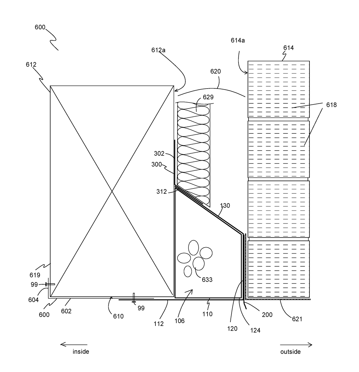
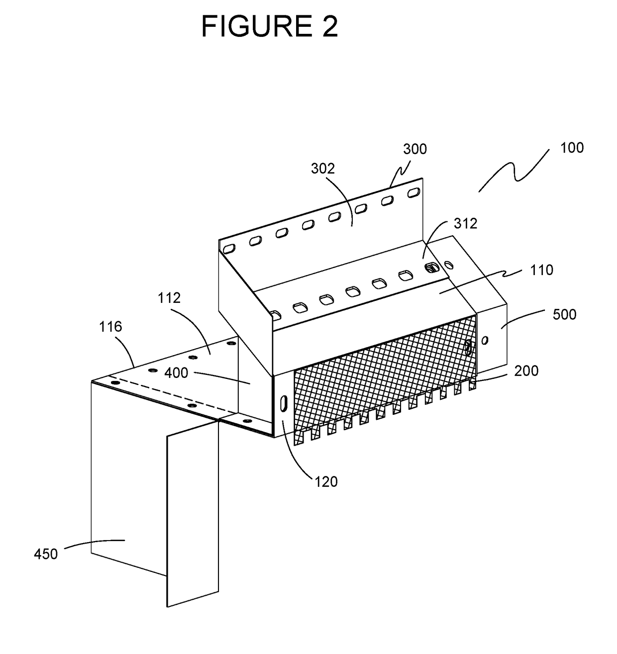
[0050]The preferred embodiments of the present invention are illustrated in FIGS. 2-9. FIG. 2 is a front, side, and top perspective view of one embodiment of a fire shield flashing system 100 of the present invention. Fire shield flashing system 100 includes a body member 110, a vertically-oriented weep fabric 200 affixed to a vertical leg 120 of body member 110, a termination member 300 with a vertical termination leg 302 that connects body member 110 to inner wythe 612 (shown in FIG. 7), and one or more optional end member 400. To connect together adjacent body members 110 and prevent water from seeping through seams between them, fire shield flashing system 100 optionally includes one or more couplers 500, each of which is installed behind and overlapping adjacent body members 110.

[0051]Although embodiments of fire shield flashing system 100 are discussed herein with reference to a masonry cavity wall, fire shield flashing system also applies to non-masonry construction having a ...


PUM


Abstract

A fenestration flashing system includes a body member having a planar header leg extending horizontally from a rearward end to a forward end, a vertical leg extending upward from the forward end of the header leg, and a positively-sloped drainage leg extending upwardly and rearwardly from a top end of the vertical leg. A termination member has a vertical termination leg for attachment to the back-up wall and a positively-sloped drainage leg to overlap and attach to the positively-sloped drainage leg of the body member. The termination member and the body member define a drainage path down and out of the wall cavity. A method of flashing a fenestration of a cavity wall or non-cavity wall is also disclosed.

Description

BACKGROUND OF THE INVENTION[0001]1. Field of Invention[0002]The present invention relates to through-wall flashing systems and fire prevention. More particularly, the present invention relates to flashing systems and methods of installing flashing systems at fenestrations in cavity wall construction.[0003]2. Description of the Related Art[0004]FIG. 1 illustrates a perspective view of a portion of a traditional masonry veneer wall 10. Traditionally, masonry wall 10 is constructed having a back-up wall or inner wythe 12 and an outer wythe 14. Inner wythe 12 is typically made of concrete masonry block 16, brick, wood, or steel frame construction elements. Outer wythe 14 is typically made of brick 18, stone, concrete block, stucco, or other cladding products. The inner and outer wythes 12, 14 are separated by a cavity 20. The width of cavity 20 can be specified by building code or architectural design preference, but is commonly dimensioned up to about six inches. Cavity 20 allows for u...

Claims


Application Information

Patent Timeline
Patent Type & Authority Applications(United States)
IPC IPC(8): E04B1/70
CPCE04B1/7053E06B2001/628E02D31/02E04B1/7046
Inventor COLLINS, PAUL MICHAELWETMORE, CRAIG
Owner YORK MFG
Why Eureka
Try Eureka