
Circuit device, oscillator, electronic apparatus, and vehicle

a technology of circuit devices and oscillators, applied in the direction of oscillator stabilization, pulse automatic control, oscillator generators, etc., can solve the problems of difficult to reduce a frequency change, inability to acquire correspondence relationship information of all oscillators which are mass-produced, etc., and achieve high-quality aging correction

Active Publication Date: 2017-07-06
SEIKO EPSON CORP
View PDF1 Cites 5 Cited by
  • Summary
  • Abstract
  • Description
  • Claims
  • Application Information

AI Technical Summary

Benefits of technology

The technical effect of this patent is to provide a circuit device, an oscillator, an electronic apparatus, a vehicle, and the like, that can realize more accurate aging correction. This is achieved by performing a calculation process of adding a correction value for compensating for a frequency change at an aging rate to a true value which is held at a timing corresponding to a hold-over detection timing. This allows for highly accurate aging correction with a simple process. Additionally, the patent describes updates to existing correction values and the reduction of the influence of element variations in system noise or observation noise on aging correction.

Problems solved by technology

In this case, the correspondence relationship information is obtained by measuring aging characteristics by operating an oscillator for a long period of time, and thus it is not possible to acquire correspondence relationship information of all oscillators which are mass-produced.
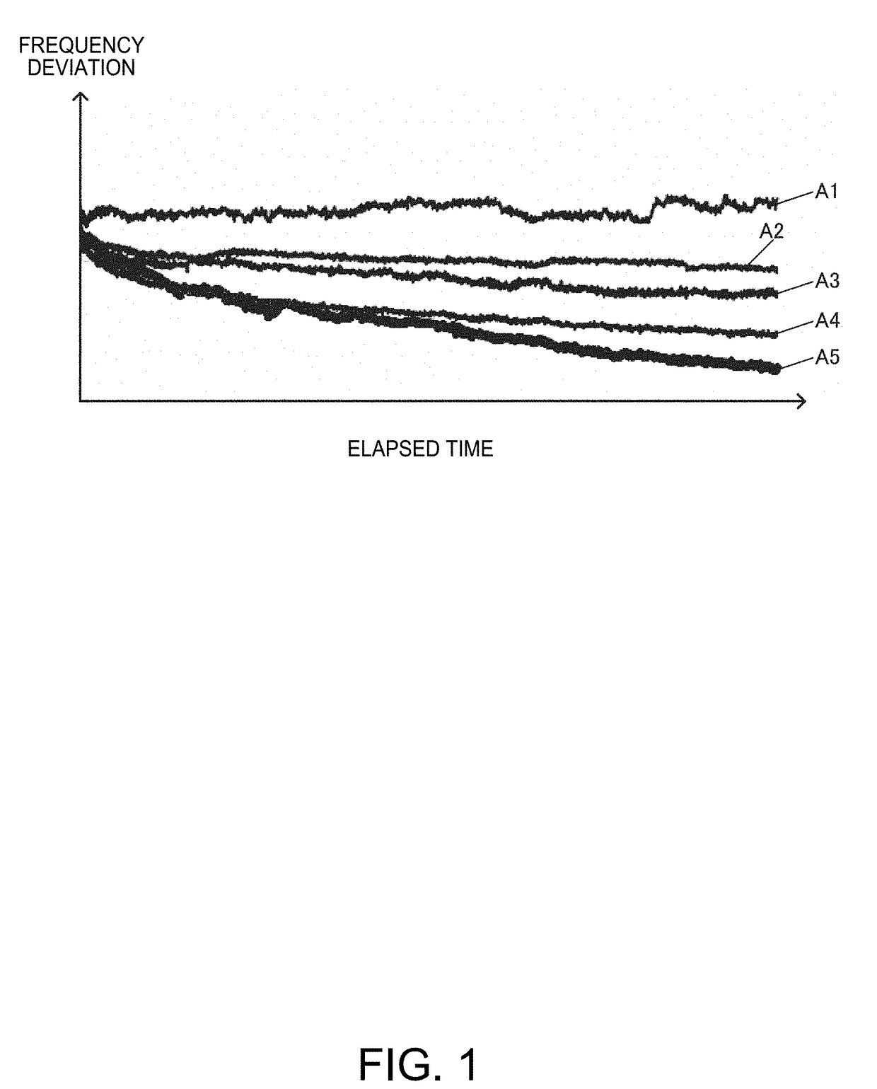
However, there is a difference in a behavior of aging change in an oscillation frequency between individual oscillators due to individual variations (hereinafter, referred to as element variations) in performance of a component forming an oscillator, a mounting state of a component or an oscillator, or a use environment of an oscillator, and it is difficult to reduce a frequency change caused by the element variations in the technique of the related art.

Method used


Image

  • Circuit device, oscillator, electronic apparatus, and vehicle
  • Circuit device, oscillator, electronic apparatus, and vehicle
  • Circuit device, oscillator, electronic apparatus, and vehicle

Examples


modification examples

7. Modification Examples

[0188]Next, various modification examples of the present embodiment will be described. FIG. 22 illustrates a configuration example of a circuit device according to a modification example of the present embodiment.

[0189]In FIG. 22, the D / A converter 80 is not provided in the oscillation signal generation circuit 140 unlike in FIG. 7. An oscillation frequency of the oscillation signal OSCK generated by the oscillation signal generation circuit 140 is directly controlled on the basis of the frequency control data DFCQ from the processor 50. In other words, an oscillation frequency of the oscillation signal OSCK is controlled without using the D / A converter.

[0190]For example, in FIG. 22, the oscillation signal generation circuit 140 a variable capacitance circuit 142 and an oscillation circuit 150. The oscillation signal generation circuit 140 is not provided with the D / A converter 80 illustrated in FIG. 7. The variable capacitance circuit 142 is provided instead...


PUM


Abstract

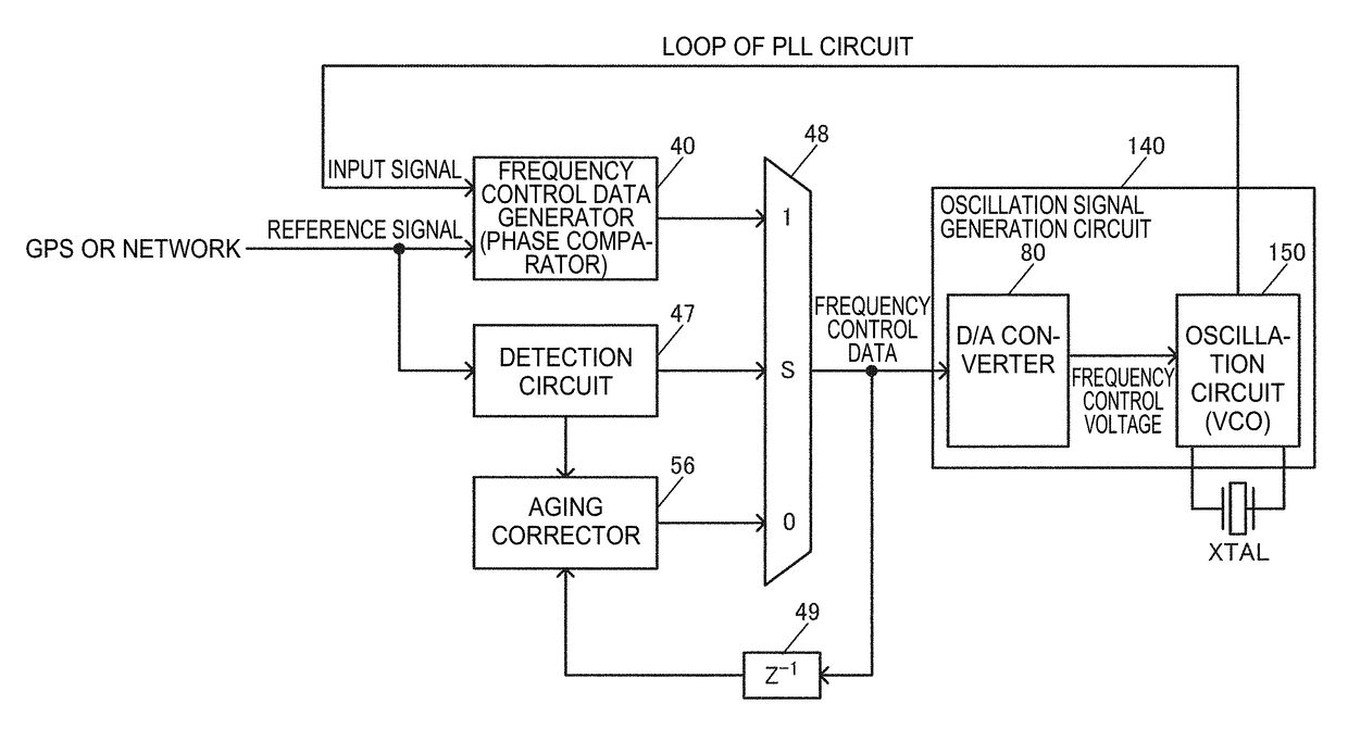
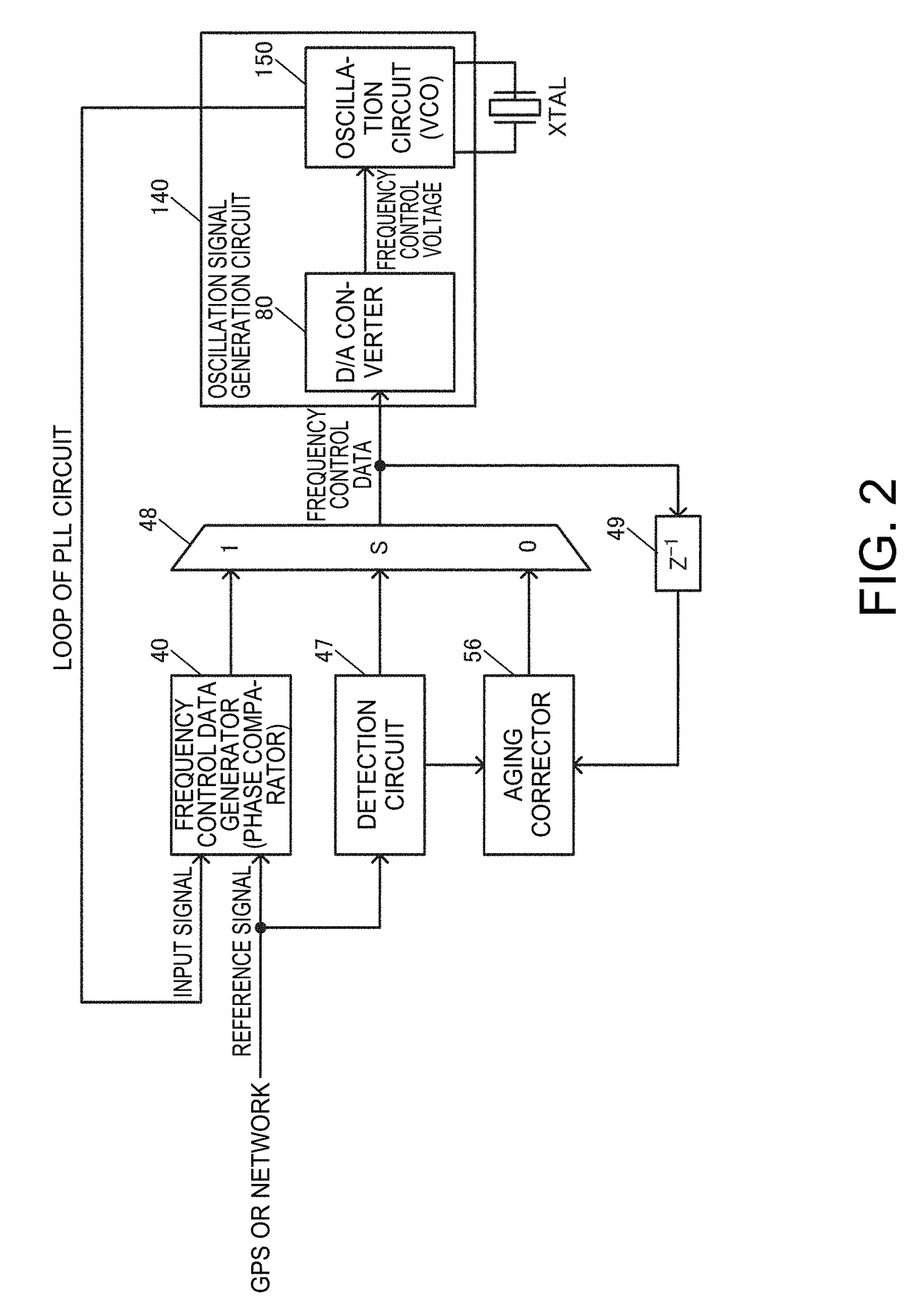
A circuit device includes an oscillation signal generation circuit that generates an oscillation signal having an oscillation frequency using a resonator, the oscillation frequency being a frequency set by using frequency control data, and a processor configured to perform a signal process on input frequency control data based on a phase comparison result between an input signal based on the oscillation signal and a reference signal. The processor is configured to estimate a true value for an observed value of the frequency control data based on the phase comparison result through a Karman filter process in a period before a hold-over state is detected, and generate aging-corrected frequency control data, in a case where the hold-over state is detected, by holding the true value at a timing corresponding to a timing of detecting the hold-over state, and by performing a calculation based on the true value.

Description

CROSS-REFERENCE TO RELATED APPLICATIONS[0001]The present application claims priority to Japanese Patent Application JP 2016-001300, filed Jan. 6, 2016, and JP 2016-137663, filed Jul. 12, 2016, the entire disclosure of which are hereby incorporated by reference herein.BACKGROUND[0002]1. Technical Field[0003]Various embodiments of the present invention relate to a circuit device, an oscillator, an electronic apparatus, and a vehicle.[0004]2. Related Art[0005]In the related art, there is an oscillator such as an oven controlled crystal oscillator (OCXO) or a temperature compensated crystal oscillator (TCXO). For example, the OCXO is used as a reference signal source in abase station, a network router, a measurement apparatus, and the like.[0006]High frequency stability is required in an oscillator such as the OCXO or the TCXO. However, a secular change called aging occurs in an oscillation frequency of an oscillator, and thus the oscillation frequency varies over time. For example, reg...

Claims


Application Information

Patent Timeline
Patent Type & Authority Applications(United States)
IPC IPC(8): H03B5/04H03B5/24H03L7/085H03B5/36
CPCH03B5/04H03B5/362H03B2200/004H03L7/085H03B5/24H03B5/368H03L1/00H03L7/18H03L7/181
Inventor YONEZAWA, TAKEMI
Owner SEIKO EPSON CORP
Learn More