Excitation device of ac exciter
a technology of exciter and exciter, which is applied in the direction of dynamo-electric machines, synchronous generators, electric generator control, etc., can solve the problems of low ac generation voltage of ac exciter, inability to make sufficient excitation in an area with low rotation speed, and complicated configuration of output circuits, etc., to achieve simple configuration
- Summary
- Abstract
- Description
- Claims
- Application Information
AI Technical Summary
Benefits of technology
Problems solved by technology
Method used
Image
Examples
first embodiment
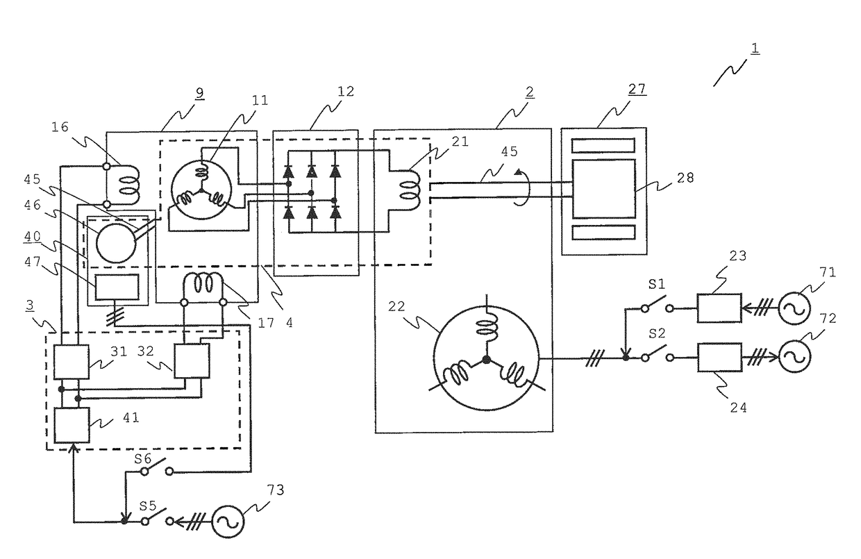
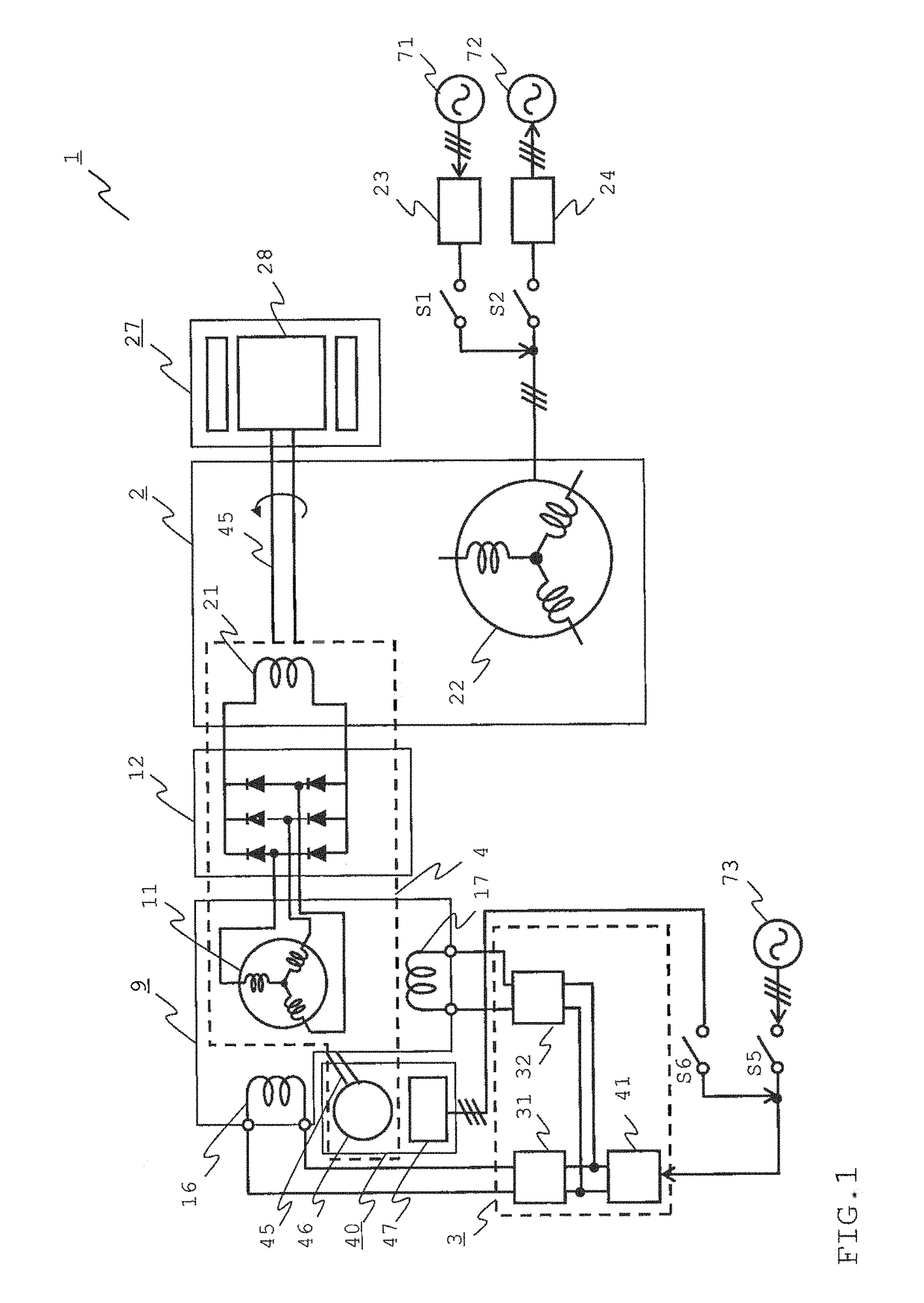
[0037]In a first embodiment, a synchronous apparatus having two field magnet winding wires of a d-axis and a q-axis is applied to a brushless excitation type exciter, as an AC exciter. Hereinafter, the first embodiment of the present invention will be described with reference to FIG. 1 to FIG. 8.
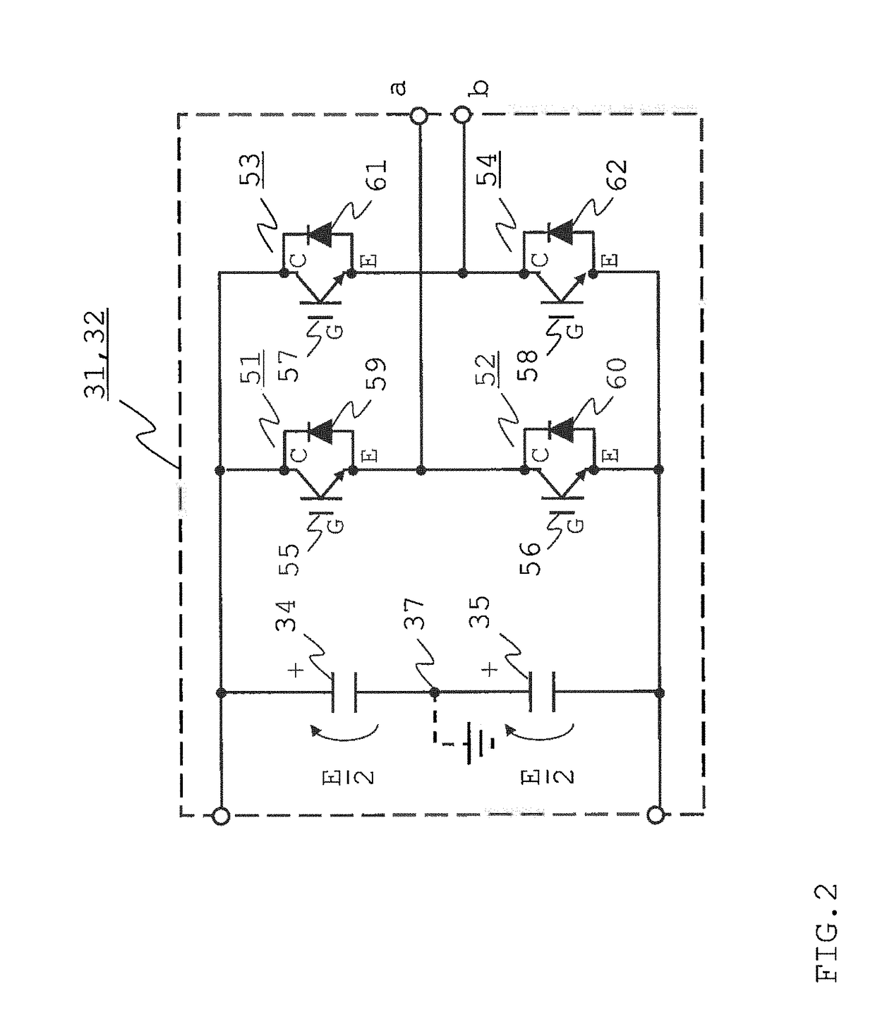
[0038]FIG. 1 is a schematic circuit configuration diagram illustrating the entirety of a gas turbine power generation system which is controlled by an AC exciter including an excitation device according to the first embodiment, FIG. 2 is a circuit diagram of a single-phase inverter of the excitation device, and FIG. 3 is another circuit diagram illustrating the single-phase inverter which is coupled to a field magnet winding wire.
[0039]First of all, a configuration of the gas turbine power generation system which is controlled by the AC exciter including the excitation device according to the first embodiment will be described with reference to FIG. 1. In FIG. 1, a gas turbine power generati...
second embodiment
[0072]FIG. 9 is a circuit diagram illustrating an operation of a single-phase inverter coupled to a field magnet winding wire which performs a DC excitation operation of an excitation device of an AC excitation according to a second embodiment. FIG. 10A to FIG. 10G illustrate output waveforms of the single-phase inverter which is controlled by a DC excitation operation of the excitation device. A difference between the circuit diagram of FIG. 9 and the circuit diagram illustrating the operation of the single-phase inverter which is performed by the DC excitation operation of the excitation device according to the first embodiment illustrated in FIG. 6 is IGBT modules which perform an ON and OFF switching operation. Circuit diagrams of the single-phase inverters are the same as those according to the first embodiment, and description thereof will be omitted.
[0073]Subsequently, circuits of the single-phase inverters 31 and 32 according to a second embodiment and an chopper operation (...
third embodiment
[0081]FIG. 12 is a diagram illustrating a drive mode logic circuit of a single-phase inverter of an excitation device of an AC exciter according to a third embodiment. In the first embodiment, the single-phase inverters respectively perform controls of the output voltages, but in the third embodiment, an input DC voltage of the single-phase inverter is controlled by a converter, and thereby an output voltage of the single-phase inverter is controlled. Other configurations are the same as those according to the first embodiment, and thus description thereof will be omitted.
[0082]As described in FIG. 12, the drive mode logic circuit of the single-phase inverter is configured by a d-axis inverter drive mode logic unit 90, a q-axis inverter drive mode logic unit 91, and a converter drive mode logic unit 92 which receive an inverter operation command and a chopper operation command.
[0083]At the time of start-up, inverter gate fixing commands are input to the d-axis inverter drive mode lo...
PUM
 Abstract
Description
Claims
Application Information
 - R&D
- Intellectual Property
- Life Sciences
- Materials
- Tech Scout
- Unparalleled Data Quality
- Higher Quality Content
- 60% Fewer Hallucinations
Browse by: Latest US Patents, China's latest patents, Technical Efficacy Thesaurus, Application Domain, Technology Topic, Popular Technical Reports.
© 2025 PatSnap. All rights reserved.Legal|Privacy policy|Modern Slavery Act Transparency Statement|Sitemap|About US| Contact US: help@patsnap.com


