Centripetal aerodynamic platform spacecraft

a spacecraft and centrifugal technology, applied in the field of aerodynamic platform spacecraft, can solve the problems of limiting the possibility of increasing the volume of passenger habitable zones and payloads per cubic foot of craft structure and surface area, requiring multiple payloads and launches, and too large space station structures and surface area, etc., to achieve the effect of reducing the required liquid oxygen and related booster tank capacity weight, reducing cost, and reducing heigh

Active Publication Date: 2017-07-06
WILLIAMS SR LAWRENCE ELLIS
View PDF2 Cites 25 Cited by
  • Summary
  • Abstract
  • Description
  • Claims
  • Application Information

AI Technical Summary

Benefits of technology

The centripetal aerodynamic platform space craft has several technical benefits. First, it includes a lower ring wing that provides stability and balance during flight and can be retracted for stealth flight mode. Second, it eliminates the long wing spans and long fusage of conventional aircraft, resulting in a lighter design that reduces launch cost. Third, it has a built-in long term habitat capabilities in space and while landed, reducing mission cost. Fourth, it creates a 1G rotating gravity environment that satisfies the need for the human body to be in environments above 15 to 20 percent of Earth's gravity to remain healthy. Fifth, it was designed with a maximum payload of 15,000 pounds and can be lifted through a heavy lift launch system. Overall, the centripetal aerodynamic platform space craft is a lighter, more efficient, and cost-effective space vehicle design.

Problems solved by technology

However, a structure of this type has to be linear and connected by ring gaskets and structural ribs to withstand exploding fuel forces at each end and stage of rockets and aerodynamic lift forces in aircraft.
This linear, cylindrical shape is meaningless and restrictive once in space and the heavy lift cylindrical can dead weight components and payload containers are abandoned to reduce weight at each launch stage to deliver a payload.
Furthermore, an approximately cylindrical stack geometry with or without wings and the related weight to surface area ratio when long wings are included limits possibilities for increasing passenger habitable zones and payload volume (carrying capacity) per cubic foot of craft structure and surface area when compared to a sphere or flattened sphere.
However space stations are too big to build and require multiple payloads and launches to construct.
The less good capability of conventional non aerodynamic structures to resist reentry and flight loads then requires increase in wing spans, structure, and generally more expensive configurations and materials with many components abandoned usually makes conventional launch and reentry systems and related aerospace exploration costly.

Method used


Image

  • Centripetal aerodynamic platform spacecraft
  • Centripetal aerodynamic platform spacecraft
  • Centripetal aerodynamic platform spacecraft

Examples


Embodiment Construction

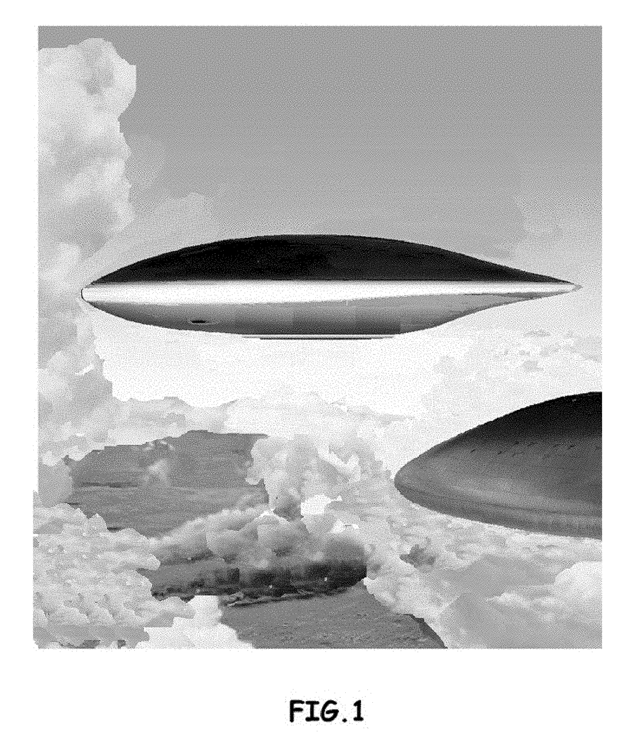
[0077]Referring now to the invention in more detail, in FIG. 1 there is shown an aerodynamic platform spacecraft, 10 with stealth properties.

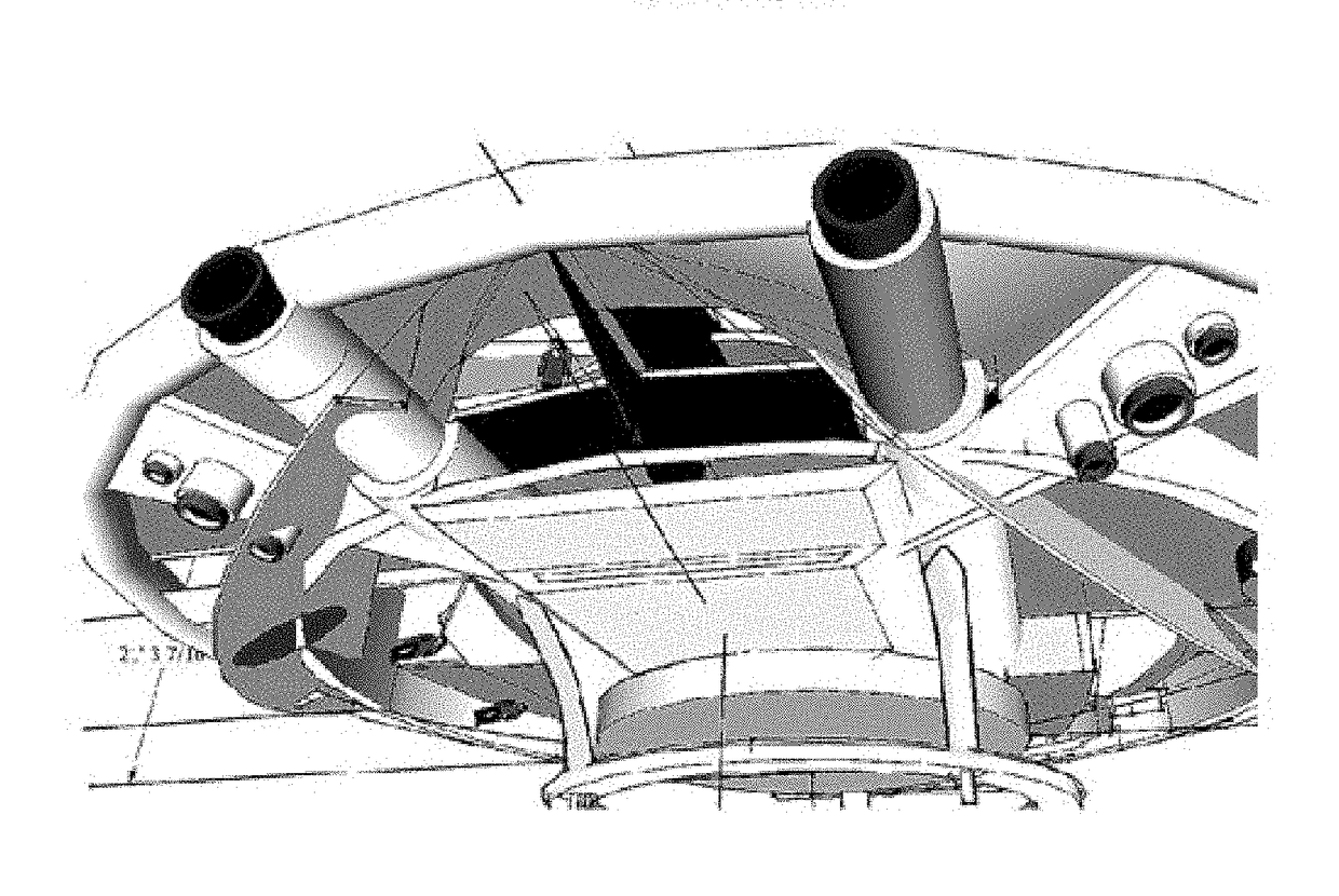
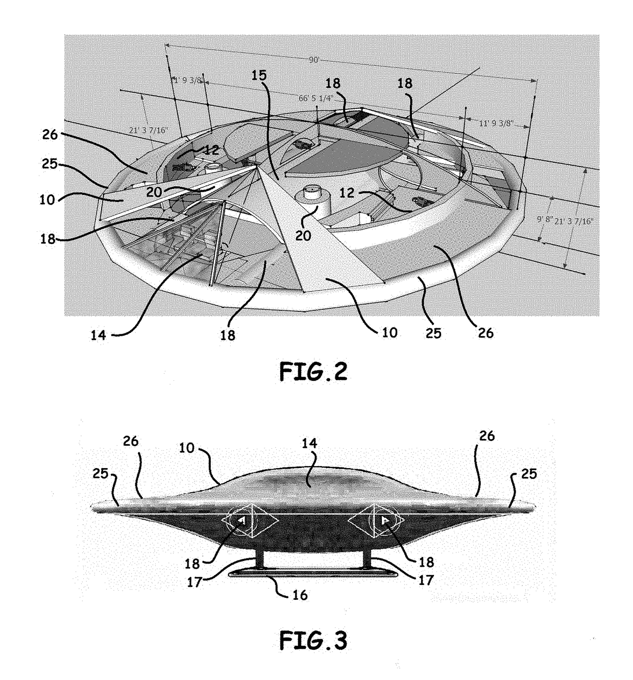
[0078]Referring now to the invention in more detail, in FIG. 2 there is shown an aerodynamic platform spacecraft, 10 having a circular centripetal rotating gravity corridor or corridors, 12 held in a substantially curved vertical position elevated or at right angle above the floor deck by an aerodynamic body, namely a lifting body, 10, a ring wing or similar under carriage wings, 16 and internal to the lift body two parallel engines, 18. The aerodynamic platform spacecraft has the ability to enter space on its own power with new industry inline hollow core turbojet-scramjet-rocket engines with shared intake and exhaust shown in FIG. 29. Two vertical lift hybrid turbojet rocket engines, 20 provide front vertical lift. Each of the components, 10, 16, 18, 20 is attached to the internal 1G producing centripetal corridor, 12 within the aerodynamic l...


PUM


Abstract

An aerodynamic platform or spacecraft including a habitable 1G centripetal force rotating gravity producing interior corridor within an aerodynamic shell and an aerodynamic drone booster launch system with reentry and reuse capability.

Description

TECHNICAL FIELD[0001]This application claims the benefit of U.S. Provisional Application No. 62 / 273,497, filed Dec. 31, 2015. This invention relates to the field of Aerospace. More particularly the present invention is in both the field of aeronautics and astronautics engineering and specifically aircraft and spacecraft design.BACKGROUND[0002]This invention applies particularly to the configuration of a structure delimiting a rotating gravity producing interior using centripetal force in orbit and deep space. The patent represents the embodiment of the first habitable, 1G, centripetal, fixed or rotating gravity ring corridor or zone inside an aerodynamic, atmospheric, reentry lift body. The 1G, centripetal gravity ring corridor, platform or area to be used by passengers of a spacecraft defines a habitable space that can also contain the pilots' cabin or cockpit and work sleep zones.[0003]The level of loads and optimized radius of a circular configuration required to achieve 1G zones...

Claims


Application Information

Patent Timeline
IPC IPC(8): B64G1/14B64D27/16F02K7/14B64C30/00B64C39/06F02K7/16B64G1/40B64G1/46
CPCB64G1/14B64G1/405B64D27/16B64G1/46F05D2220/10B64C39/06F02K7/16F02K7/14B64C30/00B64G1/12B64G1/401B64G99/00B64G1/4021B64G1/006B64G1/465B64G1/625B64G1/4005B64G1/413B64G1/402B64G1/62B64G1/002
Inventor WILLIAMS, SR., LAWRENCE ELLIS
Owner WILLIAMS SR LAWRENCE ELLIS
Why Eureka
Try Eureka