
Cables lift system for vertical pre-stresing

Inactive Publication Date: 2017-06-29
CORDERO ALEJANDRO CORTINA +2
View PDF0 Cites 14 Cited by
  • Summary
  • Abstract
  • Description
  • Claims
  • Application Information

AI Technical Summary

Benefits of technology

The invention aims to provide a pre-stressing system that is also safe for work.

Problems solved by technology

This technique is effective particularly in mid-rise structures, 5-20 meters, however, in the case of structures for nuclear reactors or towers for wind power generators, which reach above 50 m heights, such method has several drawbacks.
To reach the required height the motorized rollers require high power motors, due to the long distance the pre-stressing cables must run inside the ducts, it is common for them to jam.
The problem is increases if the structure has a reduction of diameter or waist as in the case of nuclear reactors.
The handling of the roll is complicated and risky, because the main weight of the cable lies on the roll, but not in the end that is introduced in the duct, so that at all times there is a latent risk that the roll falls under its own weight and drag the cable, tools and operators in the fall.
Moreover rise the cable roll carries a cost for the use of the crane that lifts the pre-stress cable roll.
Moreover, the layout of personnel or operators performing the post-tensioning is also a challenge.
Moreover, if the introduction of the wires is performed from the top of the tower to the bottom, the volume of equipment and pre-stressing cables become more insecure the work of the operators performing the pre-stressing.
Such a solution has various drawbacks, for example, such configuration cannot be considered since the strands have a different nature and function with respect to the pre-stressing cables which are arranged embedded in the concrete structure, within ducts, moreover, the load to be applied to said strands is very low in relation to the loads that can be applied by pre-stressing.

Method used


Image

  • Cables lift system for vertical pre-stresing
  • Cables lift system for vertical pre-stresing
  • Cables lift system for vertical pre-stresing

Examples


Embodiment Construction

[0027]The present invention finds application in lifting pre-stressing cables for concrete structures such as tanks, coolers for nuclear reactors and particularly concrete towers. In the case of concrete towers, the invention finds application in elevation of cables and pre-stressing of concrete towers sectioned as those described in U.S. Pat. No. 7,114,295 and EP-0960986A2, made by Enercon; the invention is also applicable to sectional and segmented conical towers, as those described in patents US2006 / 0156681A1 Acciona Eolica. An especially preferred tower is the triangular tower with a cylindrical extension of the same inventors hereof, which are described in detail in patents (U.S. Pat. No. 7,739,843 and U.S. Pat. No. 8,555,600).

[0028]The invention is applicable to concrete towers that are pre-stressed in the upper end of concrete, however, it is preferred that the towers include a flange for nacelle (or power generator) as the advantageous flange also developed by the inventors ...


PUM


Abstract

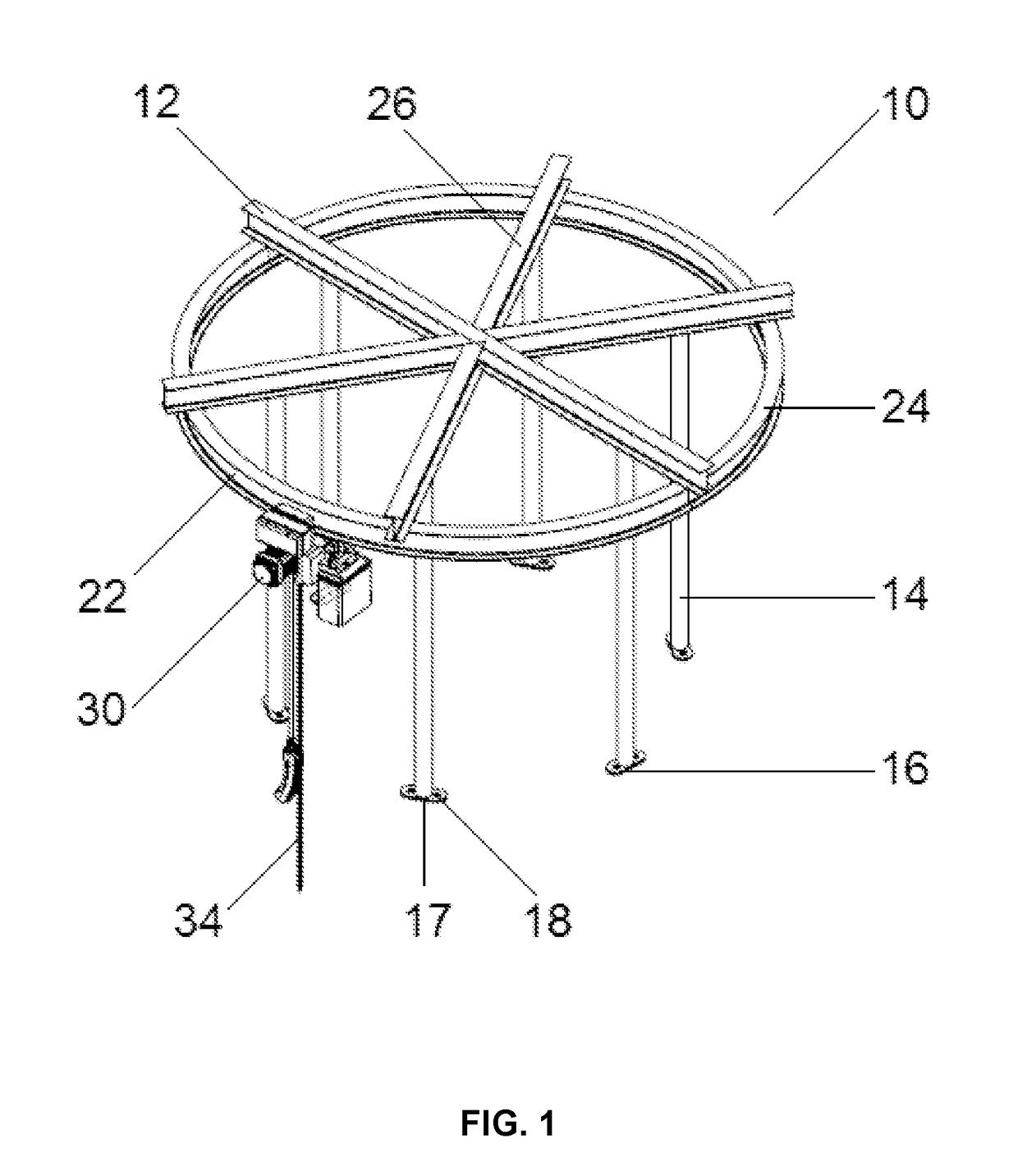
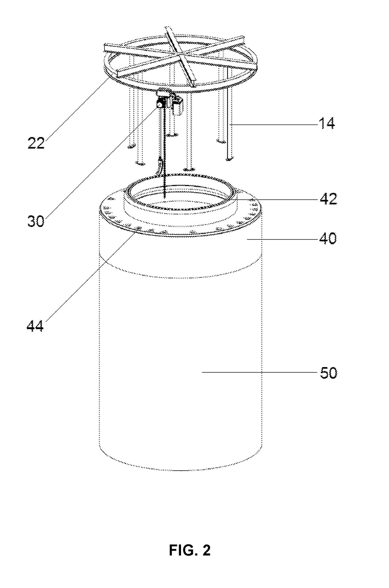
It is described an assembly for lifting pre-stressing cables for a pre-stressed concrete structure having ducts for pre-stressing cables, to be arranged on top of the concrete structure, comprising: (a) a rail 22 on which a hoist or pulley 30 is arranged, which has wheels, which allow hoist 30 to move along the rail 22; (b) a supporting structure 12, attached to rail 22; (c) a plurality of columns 14, which supports the supporting structure 12 of the rail 22, arranged at a certain distance from the rail; and (d) an hoists 30 having a chain 34 which is inserted into the vertical ducts 52 for the pre-stressing cables of the concrete structure, and uploads the wires to the top of the structure.

Description

BACKGROUND OF THE INVENTION[0001]1. Field of the Invention[0002]This description refers to a lifting system of pre-stressing cables inside of ducts in concrete structures. In particular, it relates to a lifting system for pre-stressing cables in concrete structures. More particularly for pre-stressed (pre-stressed) concrete structures of high altitude.[0003]2. General Background[0004]The pre-stressing of concrete structures requires the introduction of pre-stressing cables within ducts that are arranged inside the concrete segments mounted to form the structure. Once arranged the cables inside the ducts, cables are tensioned to exert a compressive force that holds together the concrete segments.[0005]Several pre-stressed concrete structures are known in the art. For example, tanks (U.S. Pat. No. 4,045,929), cooling towers for nuclear reactors (U.S. Pat. No. 4,092,811); Silos (U.S. Pat. No. 1,834,842) chimneys (U.S. Pat. No. 5,038,540) and other elongated structures such as concrete ...

Claims


Application Information

Patent Timeline
IPC IPC(8): E04C5/08B66C11/04E04H12/16F03D13/20E04C5/12E04H12/12
CPCE04C5/08E04C5/122B66C11/04E04H12/16F03D13/22E04H12/12E04H12/341B66C11/06B66C11/12E04G21/121Y02E10/72
Inventor CORDERO, ALEJANDRO CORTINACORDERO, JOSE PABLO CORTINAORTEGA, JOSE PABLO CORTINA
Owner CORDERO ALEJANDRO CORTINA
Learn More