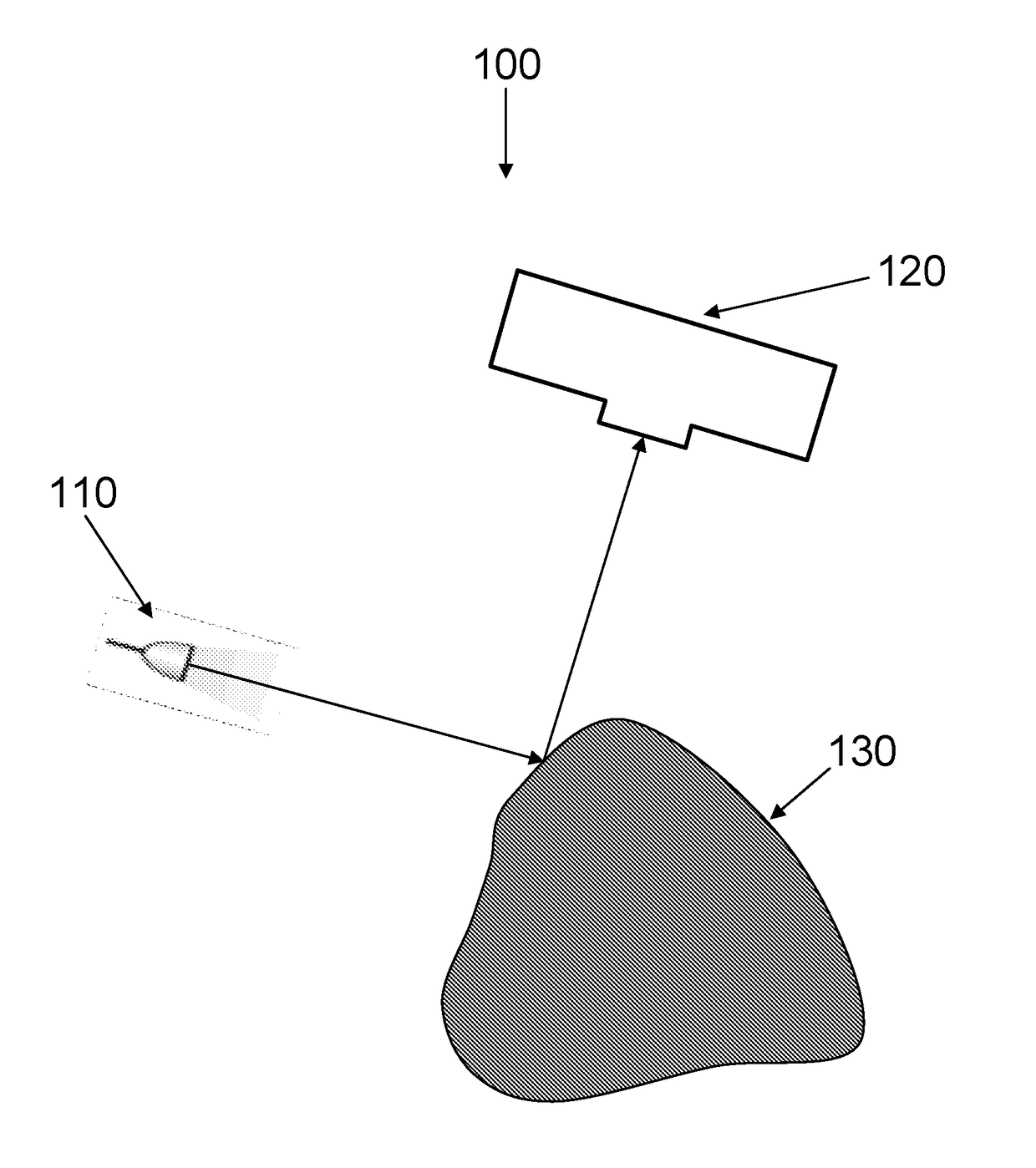
An articulated structured light based-laparoscope
a structured light and laparoscopic technology, applied in the field of providing a 3d laparoscopic image, can solve the problems of not being available in all hospitals, expensive equipment, and not being able to disclose providing a 3d image,
- Summary
- Abstract
- Description
- Claims
- Application Information
AI Technical Summary
Benefits of technology
Problems solved by technology
Method used
Image
Examples
example 1
System with Collision Avoidance System
[0820]One embodiment of such a rule-based system will comprise the following set of commands:
Detection (denoted by Gd):
Gd1 Tool location detection function
Gd2 Organ (e.g. Liver) detection function
Gd3 Movement (vector) calculation and estimation function
Gd4 Collision probability detection function
Tool Instructions (denoted Gt):
Gt1 Move according to manual command
Gt2 Stop movement
The scenario—manual move command by the surgeon:
Locations Gd1(t) and Gd2(t) are calculated in real time at each time step (from an image or location marker).
Tool movement vector Gd3(t) is calculated from Gd1(t) as the difference between the current location and at least one previous location (probably also taking into account previous movement vectors).
[0821]The probability of collision—Gd4(t)—is calculated, for example, from the difference between location Gd1 and location Gd2 (the smaller the distance, the closer the proximity and the higher the probability of collision...
example 2
System with Soft Control—Fast Movement when Nothing is Nearby, Slow Movement when Something is Close
[0828]One embodiment of such rule-based system comprises the following set of commands:
Detection (denoted by Gd):
Main Tool location detection function (denoted by GdM);
Gd-tool1-K—Tool location detection function;
Gd-organ2-L—Organ (e.g. Liver) detection function;
Gd3 Main Tool Movement (vector) calculation and estimation function;
Gd4 Proximity probability detection function;
Tool Instructions (denoted Gt):
Gt1 Movement vector (direction and speed) according to manual command
The scenario—manual move command by the surgeon:
Locations GdM(t), Gd-tool1-K(t) and Gd-organ2-L(t) are calculated in real time at each time step (from image or location marker).
Main Tool Movement Vector Gd3(t) is calculated per GdM (t) as the difference between the current location and at least one previous location (probably also taking into account previous movement vectors)
[0829]The proximity of the main tool to oth...
example 3
System with No-Fly Rule / Function
[0831]In reference to FIG. 33a-d, which shows, in a non-limiting manner, an embodiment of a tracking system with no-fly rule. The system tracks a tool 310 with respect to a no-fly zone (460), in order to determine whether the tool will enter the no-fly zone (460) within the next time step. In this example, the no-fly zone 460 surrounds the liver.
[0832]FIGS. 33a and 33b show how the behavior of the system depends on the location of the tool tip with respect to the no-fly zone, while FIGS. 33c and 33d show how movement of the tool affects the behavior.
[0833]In FIG. 33a, the tool 310 is outside the no-fly zone rule / function 460 and no movement of the tool is commanded. In FIG. 33b, the tool 310 is inside the no-fly zone 460.
[0834]The no-fly zone rule / function performs as follows:
[0835]In the embodiment illustrated, a movement 350 is commanded to move the tool 310 away from the no-fly zone 460. In some embodiments, the system prevents movement further int...
PUM
 Abstract
Description
Claims
Application Information
 - R&D
- Intellectual Property
- Life Sciences
- Materials
- Tech Scout
- Unparalleled Data Quality
- Higher Quality Content
- 60% Fewer Hallucinations
Browse by: Latest US Patents, China's latest patents, Technical Efficacy Thesaurus, Application Domain, Technology Topic, Popular Technical Reports.
© 2025 PatSnap. All rights reserved.Legal|Privacy policy|Modern Slavery Act Transparency Statement|Sitemap|About US| Contact US: help@patsnap.com


