
Spectral reading using synchronized LED sources

a technology of led sources and led sources, applied in the direction of optical radiation measurement, instruments, spectrometry/spectrophotometry/monochromators, etc., can solve the problem of limiting the amount of power that bright incident light can consum

Active Publication Date: 2017-06-15
TRUTAG TECH
View PDF0 Cites 14 Cited by
  • Summary
  • Abstract
  • Description
  • Claims
  • Application Information

AI Technical Summary

Benefits of technology

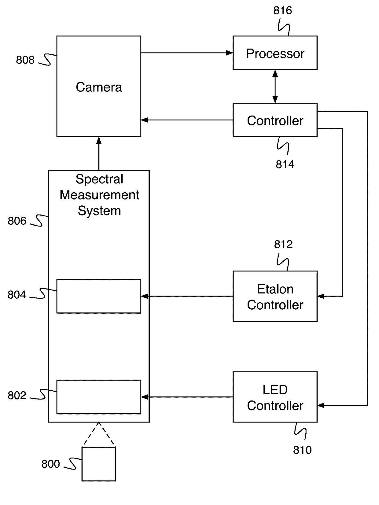
The invention is about a spectral reader that uses a tunable Fabry-Perot etalon and LED sources for accurate and reliable spectral measurements. The reader is designed to be portable and operate for a minimum time using a battery. The technical effects of the invention include improved accuracy and reliability of spectral measurements, reduced power requirements, and improved portability of the reader. The invention can be used in various applications, such as verifying items in a package or performing relative and absolute spectral measurements. The invention also includes a system for synchronizing the tunable Fabry-Perot etalon and LED sources for optimal performance. The spectral reader is designed to be compact and lightweight, with a maximum weight of 8 hours and a minimum battery requirement of 4,000 mAh. The invention also includes a method for calibrating the reader using a gap calibration table and an LED switch table for a set of gap values. Overall, the invention provides a more efficient and effective solution for performing spectral readings in various applications.

Problems solved by technology

This poses a problem when a portable reader is desired because the power requirements (e.g., those due to the powering of the bright incident light) of the reader's operations must be satisfied using a battery.
In addition, the portable reader typically needs to operate for a minimum time (e.g., 8 hours of operation) and still meet portability requirements (e.g., a maximum weight), which set limits on the amount of power that the bright incident light can consume.

Method used


Image

  • Spectral reading using synchronized LED sources
  • Spectral reading using synchronized LED sources
  • Spectral reading using synchronized LED sources

Examples


Embodiment Construction

[0031]The invention can be implemented in numerous ways, including as a process; an apparatus; a system; a composition of matter; a computer program product embodied on a computer readable storage medium; and / or a processor, such as a processor configured to execute instructions stored on and / or provided by a memory coupled to the processor. In this specification, these implementations, or any other form that the invention may take, may be referred to as techniques. In general, the order of the steps of disclosed processes may be altered within the scope of the invention. Unless stated otherwise, a component such as a processor or a memory described as being configured to perform a task may be implemented as a general component that is temporarily configured to perform the task at a given time or a specific component that is manufactured to perform the task. As used herein, the term ‘processor’ refers to one or more devices, circuits, and / or processing cores configured to process da...


PUM


Abstract

A system for spectral reading includes a plurality of LEDs, an interface, and a processor. The plurality of LEDs are disposed in a physical array. Light from the plurality of LEDs is enabled to be collimated at a Fabry-Perot etalon. The interface is configured to receive a gap calibration table and power characteristics of a plurality of LEDs. The processor is configured to determine an LED switch table. The LED switch table indicates a set of the plurality of LEDs with power above a threshold at a plurality of wavelengths. The processor is further configured to cause measurement of a sample using the gap calibration table and the LED switch table for a set of gap values and determine measurement results.

Description

CROSS REFERENCE TO OTHER APPLICATIONS[0001]This application claims priority to U.S. Provisional Patent Application No. 62 / 267,753 entitled SPECTRAL READING USING SYNCHRONIZED LED SOURCES filed Dec. 15, 2015 which is incorporated herein by reference for all purposes.BACKGROUND OF THE INVENTION[0002]A reader is used to measure a reflected optical spectrum from objects. In order to produce a strong reflected signal, a bright incident light is used. This poses a problem when a portable reader is desired because the power requirements (e.g., those due to the powering of the bright incident light) of the reader's operations must be satisfied using a battery. In addition, the portable reader typically needs to operate for a minimum time (e.g., 8 hours of operation) and still meet portability requirements (e.g., a maximum weight), which set limits on the amount of power that the bright incident light can consume.BRIEF DESCRIPTION OF THE DRAWINGS[0003]Various embodiments of the invention are...

Claims


Application Information

Patent Timeline
IPC IPC(8): G01J3/26G01J3/10H05B33/08G01J3/02H05B44/00
CPCG01J3/26G01J3/0275G01J2003/106G01J3/108H05B33/0857G01J3/10G01J3/027H05B45/20
Inventor LEARMONTH, TIMOTHYFINKELSTEIN, HOD
Owner TRUTAG TECH
Learn More