
Pre-Cooling of Natural Gas by High Pressure Compression and Expansion

a compression expansion and high pressure technology, applied in the field of liquefaction of natural gas, can solve the problems of increasing the loss prevention issue of flng, significant technical challenges remain in the application of the technology, and the capacity limitation of the smr process

Inactive Publication Date: 2017-06-15
PIERRE JR FRITZ
View PDF5 Cites 32 Cited by
  • Summary
  • Abstract
  • Description
  • Claims
  • Application Information

AI Technical Summary

Benefits of technology

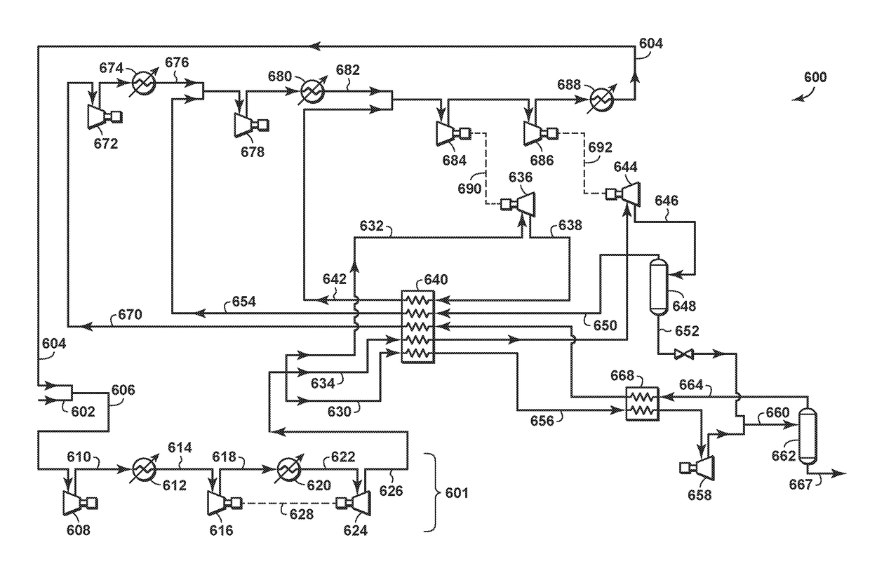
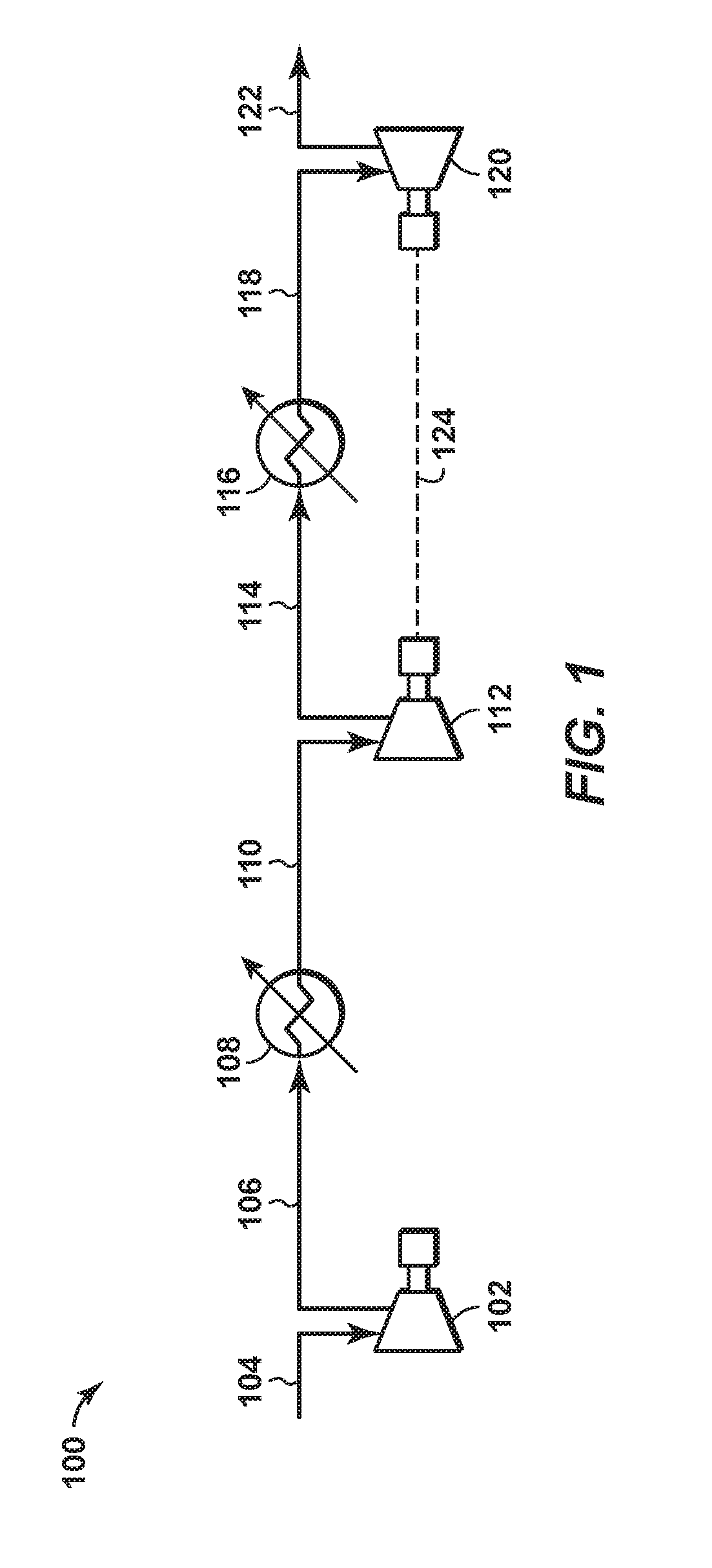
The patent describes a method and apparatus for producing liquefied natural gas (LNG) from a natural gas stream. The method involves compressing the natural gas stream with at least two serially arranged compressors to a pressure of at least 2,000 psia, cooling it with a cooling element to form a cooled compressed natural gas stream, and expanding it in a work-producing expander to a pressure of no greater than 3,000 psia to produce a chilled natural gas stream. The chilled natural gas stream is then liquefied using a liquefaction train. The invention also provides a floating LNG structure that includes the components of the production system described above. The technical effect of the invention is to efficiently produce LNG from natural gas in a compact space and with minimal energy usage.

Problems solved by technology

FLNG is a technology solution for monetizing offshore stranded gas where it is not economically viable to construct a gas pipeline to shore.
Although FLNG has several advantageous over conventional onshore LNG, significant technical challenges remain in the application of the technology.
For example, the required use and storage of combustible refrigerants such as propane significantly increases loss prevention issues on the FLNG.
The SMR process is also limited in capacity, which increases the number of trains needed to reach the desired LNG production.
For these reasons and others, a significant amount of topside space and weight is required for the SMR trains.
However, application of the expander-based process to an FLNG project with LNG production of greater than 2 million tons per year (MTA) has proven to be less appealing than the use of the mixed refrigerant process.
The size of the expander-based process train is limited since its refrigerant mostly remains in the vapor state throughout the entire process and the refrigerant absorbs energy through its sensible heat.
Furthermore, the limitations in compander horsepower size results in parallel rotating machinery as the capacity of the expander-based process train increases.
However, the equipment count, complexity and cost all increase with multiple expander trains.
This technology requires smaller equipment and topside space than a dual loop nitrogen expander-based process.
The technology, however, is still limited to a capacity of less than 1.5 MTA.
However, the technology has the disadvantage of a high equipment count and increased complexity due to its requirement for two independent refrigeration loops and the compression of the feed gas.
Furthermore, the high pressure operation also means that the equipment and piping will be much heavier than that of other expander-based processes.
According to this document, including a liquefying expander in the process significantly reduces the recycle gas rate and the overall required refrigeration power.
However, the technology is still limited to capacity of less than 1.5 MTA and it requires the use of liquefying expander, which is not standard equipment for LNG production.
The technology has also been shown to be less efficient than other technologies for the liquefaction of lean natural gas.
The carbon dioxide refrigeration circuit, however, comes at the cost of added complexity to the liquefaction process since an additional refrigerant and a substantial amount of extra equipment is introduced.
This arrangement has the disadvantage of requiring a significant amount of pipe connections between the pre-cooling module and the main expander-based process modules.

Method used


Image

  • Pre-Cooling of Natural Gas by High Pressure Compression and Expansion
  • Pre-Cooling of Natural Gas by High Pressure Compression and Expansion
  • Pre-Cooling of Natural Gas by High Pressure Compression and Expansion

Examples


Embodiment Construction

[0025]Various specific aspects, embodiments, and versions will now be described, including definitions adopted herein. Those skilled in the art will appreciate that such aspects, embodiments, and versions are exemplary only, and that the invention can be practiced in other ways. Any reference to the “invention” may refer to one or more, but not necessarily all, of the embodiments defined by the claims. The use of headings is for purposes of convenience only and does not limit the scope of the present invention. For purposes of clarity and brevity, similar reference numbers in the several Figures represent similar items, steps, or structures and may not be described in detail in every Figure.

[0026]All numerical values within the detailed description and the claims herein are modified by “about” or “approximately” the indicated value, and take into account experimental error and variations that would be expected by a person having ordinary skill in the art.

[0027]As used herein, the te...


PUM


Abstract

A method of producing liquefied natural gas (LNG) is disclosed. A natural gas stream is provided from a supply of natural gas. The natural gas stream is compressed in at least two serially arranged compressors to a pressure of at least 2,000 psia to form a compressed natural gas stream. The compressed natural gas stream is cooled to form a cooled compressed natural gas stream. The cooled compressed natural gas stream is expanded in at least one work producing natural gas expander to a pressure that is less than 3,000 psia and no greater than the pressure to which the at least two serially arranged compressors compress the natural gas stream, to thereby form a chilled natural gas stream. The chilled natural gas stream is liquefied.

Description

CROSS REFERENCE TO RELATED APPLICATIONS[0001]This application claims the benefit of U.S. Provisional Patent Application 62 / 266,985, filed Dec. 14, 2015 entitled PRE-COOLING OF NATURAL GAS BY HIGH PRESSURE COMPRESSION AND EXPANSION, the entirety of which is incorporated by reference herein.[0002]This application is related to U.S. Provisional Patent Application No. 62 / 266,976 titled “Method and System for Separating Nitrogen from Liquefied Natural Gas Using Liquefied Nitrogen;” U.S. Provisional Patent Application No. 62 / 266,979 titled “Expander-Based LNG Production Processes Enhanced With Liquid Nitrogen;” and U.S. Provisional Patent Application No. 62 / 266,983 titled “Method of Natural Gas Liquefaction on LNG Carriers Storing Liquid Nitrogen;” all having common inventors and assignee and filed on an even date herewith, the disclosure of which is incorporated by reference herein in their entirety.FIELD OF THE INVENTION[0003]The invention relates to the liquefaction of natural gas to f...

Claims


Application Information

Patent Timeline
IPC IPC(8): F25J1/00F25J1/02
CPCF25J1/0022F25J2290/72F25J1/0092F25J1/0202F25J1/0225F25J1/0037F25J2270/90F25J2290/12F25J2205/02F25J2210/06F25J2245/02F25J2210/60F25J2230/24F25J2230/30F25J2230/60F25J2230/04F25J2230/20F25J2240/04F25J2270/06F25J2270/08F25J1/004F25J1/0035F25J1/0042F25J1/005F25J1/0072F25J1/0204F25J1/0212F25J1/0254F25J1/027F25J1/0278F25J1/0288F25J1/0283F25J2240/80F25J2230/22
Inventor PIERRE, JR., FRITZ
Owner PIERRE JR FRITZ
Learn More