
Cooling system for vehicle

a technology for cooling systems and vehicles, applied in the direction of machines/engines, mechanical equipment, transportation and packaging, etc., can solve the problems of increased weight, increased manufacturing cost, and deterioration of productivity, so as to reduce the number of constituent elements, reduce weight and manufacturing cost, and improve spatial utility

Active Publication Date: 2017-06-15
HYUNDAI MOTOR CO LTD +1
View PDF8 Cites 10 Cited by
  • Summary
  • Abstract
  • Description
  • Claims
  • Application Information

AI Technical Summary

Benefits of technology

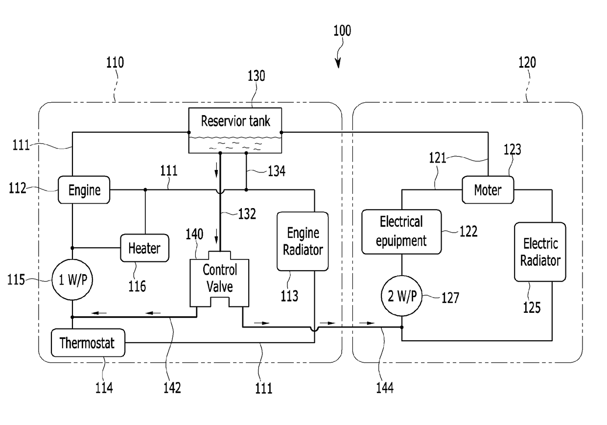
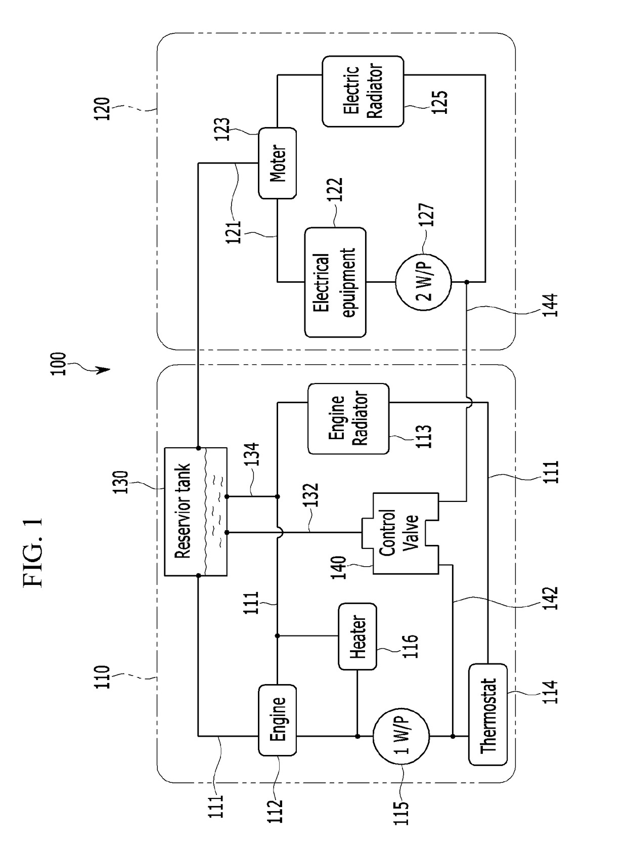
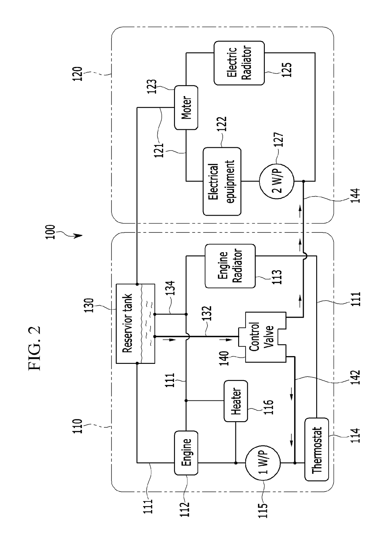
The present invention provides a cooling system for a vehicle that reduces the number of components, weight, and manufacturing costs. By combining the engine cooling circuit and electronics cooling circuit, coolant is injected into one tank, which simplifies the cooling system and reduces the space needed in the engine compartment. A control valve prevents coolant from flowing to the electronics circuit during warm driving. The system also reduces the time needed for the reservoir tank to be mounted and improves productivity.

Problems solved by technology

Accordingly, as two reservoir tanks must be provided for the circuits, they are difficult to be mounted in a narrow engine compartment, and a manufacturing cost is increased due to the large number of constituent elements.
Also, the weight is increased due to the large number of constituent elements, and productivity may be deteriorated by requiring a mounting time of each reservoir tank.

Method used


Image

  • Cooling system for vehicle
  • Cooling system for vehicle
  • Cooling system for vehicle

Examples


Embodiment Construction

[0029]It is understood that the term “vehicle” or “vehicular” or other similar term as used herein is inclusive of motor vehicles in general such as passenger automobiles including sports utility vehicles (SUV), buses, trucks, various commercial vehicles, watercraft including a variety of boats and ships, aircraft, and the like, and includes hybrid vehicles, electric vehicles, plug-in hybrid electric vehicles, hydrogen-powered vehicles and other alternative fuel vehicles (e.g. fuels derived from resources other than petroleum). As referred to herein, a hybrid vehicle is a vehicle that has two or more sources of power, for example both gasoline-powered and electric-powered vehicles.

[0030]The terminology used herein is for the purpose of describing particular embodiments only and is not intended to be limiting of the invention. As used herein, the singular forms “a,”“an” and “the” are intended to include the plural forms as well, unless the context clearly indicates otherwise. It will...


PUM


Abstract

A cooling system for a vehicle includes: an engine cooling circuit circulating a coolant to an engine mounted in the vehicle; an electronics cooling circuit circulating the coolant to an electrical equipment and a motor mounted in the vehicle; a reservoir tank connected to the engine and the motor and respectively compensating the coolant to the engine cooling circuit and the electronics cooling circuit; and a control valve connected to a first connection pipe connected to the reservoir tank and selectively connected to the engine cooling circuit and the electronics cooling circuit depending on a temperature change of the coolant during a cold driving mode or a warm driving mode of the vehicle to control a flow of the coolant.

Description

CROSS-REFERENCE TO RELATED APPLICATION[0001]This application claims under 35 U.S.C. §119(a) the benefit of Korean Patent Application No. 10-2015-0176337 filed in the Korean Intellectual Property Office on Dec. 10, 2015, the entire contents of which are incorporated herein by reference.BACKGROUND[0002](a) Field of the Invention[0003]The present invention relates to a cooling system for a vehicle, more particularly, to a cooling system configured to inject a coolant to one reservoir tank in conjunction with an engine cooling circuit and an electronics cooling circuit.[0004](b) Description of the Related Art[0005]Recently, development of environmentally-friendly vehicles has advanced with a goal of substantially replacing internal combustion engine vehicles. In general, an environmentally-friendly vehicle is classified into an electric vehicle that is driven using a fuel cell or electricity as a power source, and a hybrid vehicle that is driven using an engine and an electric battery.[...

Claims


Application Information

Patent Timeline
Patent Type & Authority Applications(United States)
IPC IPC(8): F01P7/16F01P11/04F01P5/10B60K11/02F01P3/20
CPCF01P7/167B60K11/02F01P11/04F01P5/10F01P3/20F01P7/165F01P11/00F01P11/16F01P2007/146F01P2060/18F01P2050/24B60Y2200/92
Inventor KIM, JAE YEONCHO, WAN JEKIM, YEON HOPARK, JONG MAN
Owner HYUNDAI MOTOR CO LTD
Learn More