Phosphor, wavelength conversion element, light source device, and projector

Active Publication Date: 2017-06-08
SEIKO EPSON CORP
View PDF3 Cites 15 Cited by
  • Summary
  • Abstract
  • Description
  • Claims
  • Application Information

AI Technical Summary

Benefits of technology

The invention is about a new type of phosphor that can be used in a light source device for projectors. This phosphor has a void which helps scatter light and increases thermal conductivity, making it better at conducting heat. When this phosphor is used in a light source device, it results in a more reliable and effective projector.

Problems solved by technology

However, the heat resistance of the organic material is lower than that of an inorganic material, and therefore, when the binder is irradiated with high-intensity laser light as excitation light, the binder is degraded by heat.
Due to this, when the phosphor is irradiated with high-intensity laser light as excitation light, heat is accumulated therein, and the luminous efficiency of the phosphor particles is deteriorated.
Further, the more voids are included in the phosphor, the more easily the phosphor is broken, and therefore, there is a possibility that the phosphor is broken by thermal stress.
Further, when excitation light is converged and irradiated on a narrow region so as to use the phosphor as a point light source, the temperature of the phosphor becomes high at the excitation light irradiation position, and therefore, large thermal stress is generated.
However, in the case where an optical functional layer is formed on the phosphor layer disclosed in Patent Document 2 having concave portions on the surface, it is difficult to form the optical functional layer in an intended state in the concave portions, and it is difficult to form the optical functional layer having intended properties.

Method used


Image

  • Phosphor, wavelength conversion element, light source device, and projector
  • Phosphor, wavelength conversion element, light source device, and projector
  • Phosphor, wavelength conversion element, light source device, and projector

Examples


first embodiment

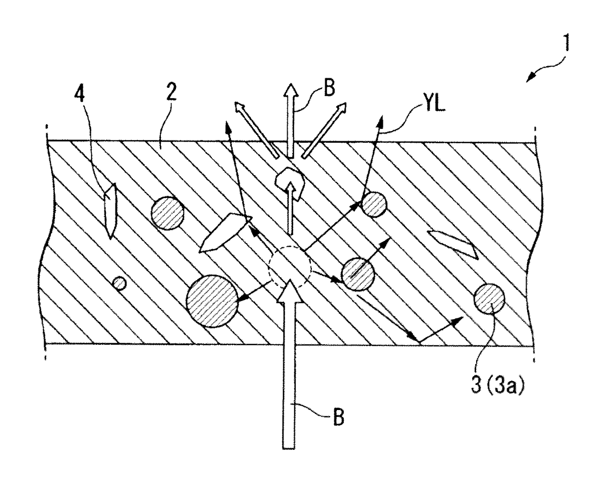
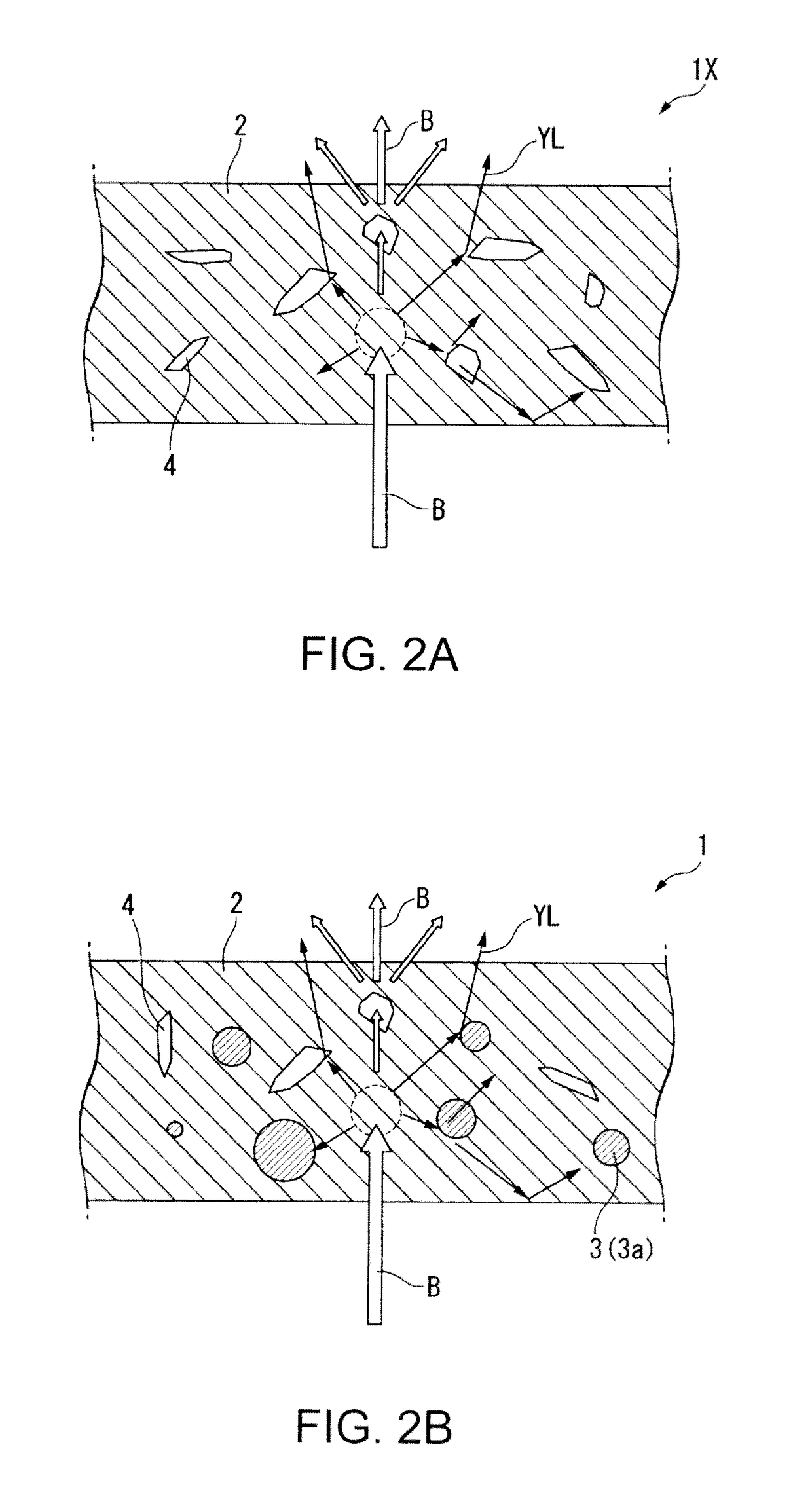
[0082]Hereinafter, a phosphor, a wavelength conversion element, a light source device, and a projector according to this embodiment will be described with reference to the drawings. In all the drawings described below, in order to make the drawings easy to see, the dimensions, ratios, and the like of the respective constituent elements are appropriately made different from the actual ones.

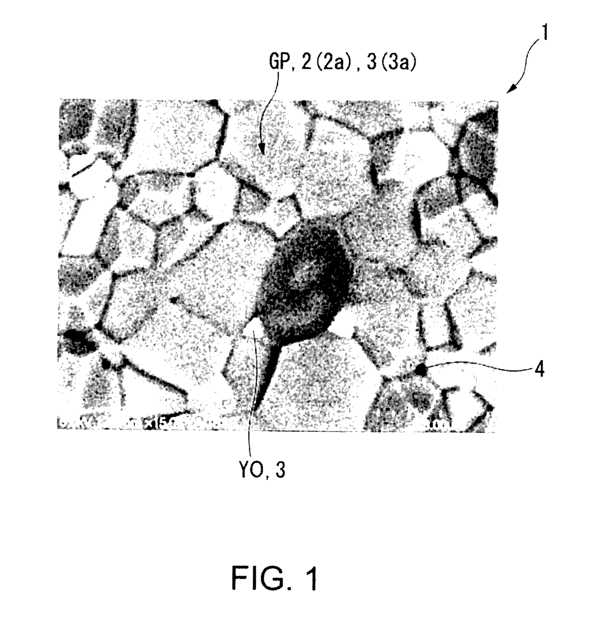
[0083]FIG. 1 is an SEM image showing one example of a phosphor of this embodiment and is a backscattering electron image (BSE image). A phosphor 1 of this embodiment is composed of a sintered body of a ceramic material.

[0084]The phosphor 1 contains Ce:Y3Al5O12 (hereinafter referred to as “Ce:YAG”) as a main phase 2 and two types of ceramic materials as a subphase 3. The two types of ceramic materials are Ce:YAlO3, (hereinafter referred to as “Ce:YAP”) and Ce:Y2O3. Further, the phosphor 1 contains a plurality of voids 4.

[0085]In FIG. 1, a crystal grain composed of Ce:Y2O3 is represented by a symbol ...

second embodiment

[0199]Hereinafter, a wavelength conversion element, a light source device, and a projector according to a second embodiment will be described with reference to FIGS. 14 to 19B.

[0200]FIG. 14 is a schematic view showing a projector 1000M according to this embodiment. The projector 1000M is different from the projector 1000 according to the first embodiment in that it includes a light source device 100M in place of the above-mentioned light source device 100. The light source device 100M is different from the light source device 100 in that it includes a wavelength conversion element 30M in place of the above-mentioned wavelength conversion element 30. The other configuration is the same as that of the projector 1000, and therefore, the same elements as in FIG. 3 are denoted by the same reference numerals and signs, and a detailed description thereof will be omitted.

[0201]The light source device 100M includes a light source 10, a condenser optical system 20, a wavelength conversion ele...


PUM

PropertyMeasurementUnit
Volumeaaaaaaaaaa
Shapeaaaaaaaaaa
Antireflectiveaaaaaaaaaa

Abstract

A phosphor includes a sintered body of a ceramic material. The sintered body contains Ce:Y3Al5O12 as a main phase and a ceramic material as a subphase. The ceramic material has a refractive index different from that of the main phase. The sintered body has a crystal grain boundary and a void at the crystal grain boundary.

Description

BACKGROUND[0001]1. Technical Field[0002]The present invention relates to a phosphor, a wavelength conversion element, a light source device, and a projector.[0003]2. Related Art[0004]JP-A-2009-277516 (Patent Document 1) describes a light source device utilizing fluorescence emitted from a phosphor as illumination light. This phosphor includes a binder composed of an organic material and phosphor particles dispersed in the binder. However, the heat resistance of the organic material is lower than that of an inorganic material, and therefore, when the binder is irradiated with high-intensity laser light as excitation light, the binder is degraded by heat.[0005]JP-T-2013-518172 (Patent Document 2) discloses an inorganic phosphor which does not contain an organic material. The inorganic phosphor is obtained by sintering a plurality of phosphor particles.[0006]However, the phosphor disclosed in Patent Document 2 has a plurality of voids, and therefore, the thermal conductivity of the pho...

Claims


Application Information

Patent Timeline
IPC IPC(8): G03B21/20C04B35/10F21V9/16C09K11/77G03B21/00G03B21/16
CPCG03B21/204G03B21/005G03B21/16F21V9/16C09K11/7774C04B2235/9646C04B2235/3225C04B2235/3229C04B2235/3222C04B2235/85C04B35/10C04B35/44H04N9/3105H04N9/3158H04N9/3161C04B2235/764C04B2235/80
Inventor IKESUE, AKIOENDO, TAKASHI
Owner SEIKO EPSON CORP
Why Eureka
Try Eureka