End seal structure of fuel rail for gasoline direct-injection engine

Active Publication Date: 2017-06-08
USUI KOKUSAI SANGYO KAISHA LTD
View PDF9 Cites 5 Cited by
  • Summary
  • Abstract
  • Description
  • Claims
  • Application Information

AI Technical Summary

Problems solved by technology

However, the above-mentioned conventional fuel rails for gasoline direct injection engines have the following problems.

Method used


Image

  • End seal structure of fuel rail for gasoline direct-injection engine
  • End seal structure of fuel rail for gasoline direct-injection engine
  • End seal structure of fuel rail for gasoline direct-injection engine

Examples


Embodiment Construction

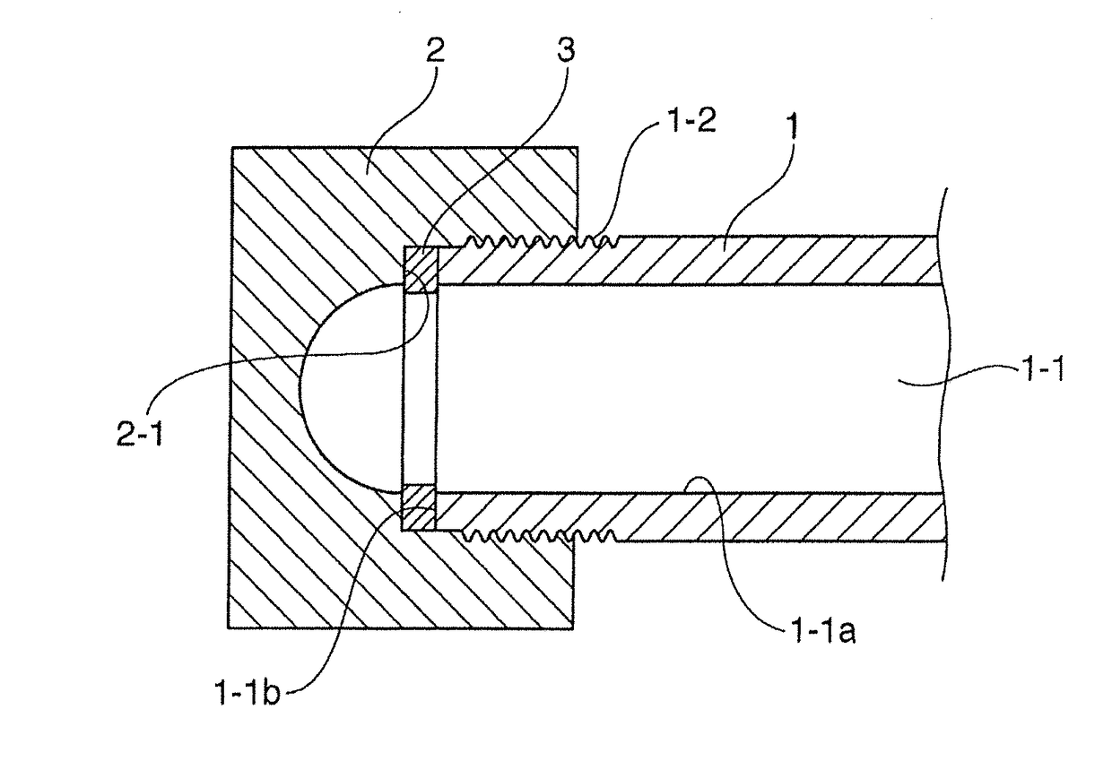
[0014]A main pipe rail in accordance with the present invention is a main body of a fuel rail for gasoline direct injection engines, in which a fuel inlet pipe (not shown) is connected to one end or a wall surface of the main pipe rail, the fuel inlet pipe is connected by a piping (not shown) to a fuel tank (not shown), fuel of the fuel tank is transferred to the fuel inlet pipe through the piping and a fuel pump, made to flow from the fuel inlet pipe to the main pipe rail, and then injected from an injector (not shown) into a cylinder (not shown). The main pipe rail 1 includes a plurality of sockets (not shown) or the like in its circumferential wall portion, the socket being adapted to allow the injector to be connected thereto. By way of example, a four-cylinder engine and an in-line six-cylinder engine will be equipped with four sockets and six sockets, respectively, which are provided at desired intervals.

[0015]In FIG. 1, a reference sign 1 denotes a rail body 1, a reference si...


PUM


Abstract

Provided is an end seal structure of a fuel rail for a gasoline direct injection engine, in which an end or both ends of a rail body composed of a pipe is/are closed by a thread fastening type of an end cap or end caps having a cap-nut shape, is characterized in that a metallic gasket is provided between an inner wall surface of the end cap having the cap-nut shape and an end section of the rail body, the end cap having the cap-nut shape is screwed and fixed to the rail body, and the gasket is tightened by an axial force created by tightening of the end cap having the cap-nut shape so that the end of the rail body is sealed.

Description

BACKGROUND[0001]1.Field of the Invention[0002]The present invention relates to an end seal structure of a fuel rail (delivery pipe) for supplying high-pressure fuel, which is supplied from fuel booster pumps of electronic fuel injection-type automobile engines or the like, through a fuel injector (an injection nozzle) directly injecting the fuel into an engine cylinder. More specifically, the present invention relates to an end seal structure of a fuel rail for a gasoline direct injection engine configured to directly supply the fuel from the rail to the injector with an injection pressure in the order of 20 MPa to 70 MPa.[0003]2.Description of the Related Art[0004]Some exemplary fuel rails can be mentioned as the conventional fuel rails for gasoline direct injection engines of this type. For example, an exemplary fuel rail includes a main pipe and several branch pipes and is constructed and arranged such that through-holes for receiving each branch pipe are formed in an outer wall ...

Claims


Application Information

Patent Timeline
Patent Type & Authority Applications(United States)
IPC IPC(8): F02M55/00F02M55/02
CPCF02M55/025F02M55/005F02M55/004F02M55/02Y10S277/941
Inventor ASAHI, DAISUKE
Owner USUI KOKUSAI SANGYO KAISHA LTD
Why Eureka
Try Eureka