
Pod propulsion device and a method for cooling such

a pod propulsion and cooling device technology, applied in the direction of marine propulsion, magnetic circuit shape/form/construction, vessel construction, etc., can solve the problems of circumstantial and space-consuming provision of special cooling ducts for cooling the hot spot, and the pod propulsion device using an electric motor for driving the propeller shaft generates a substantial amount of heat, so as to improve the cooling effect and minimize the drawbacks

Active Publication Date: 2017-06-08
KONGSBERG MARITIME SWEDEN AB
View PDF2 Cites 2 Cited by
  • Summary
  • Abstract
  • Description
  • Claims
  • Application Information

AI Technical Summary

Benefits of technology

The invention is a pod propulsion device that cools down the device effectively to prevent overheating. The method is easy to install and works well. It also takes up less space in the strut.

Problems solved by technology

A pod propulsion device using an electric motor for driving the propeller shaft generates a substantial amount of heat.
This is of course not a cost effective solution.
The provision of special cooling ducts for cooling the hot spot is circumstantial and space consuming, in particular since cooling ducts also are required to cool other parts of the electric motor.

Method used


Image

  • Pod propulsion device and a method for cooling such
  • Pod propulsion device and a method for cooling such
  • Pod propulsion device and a method for cooling such

Examples


Embodiment Construction

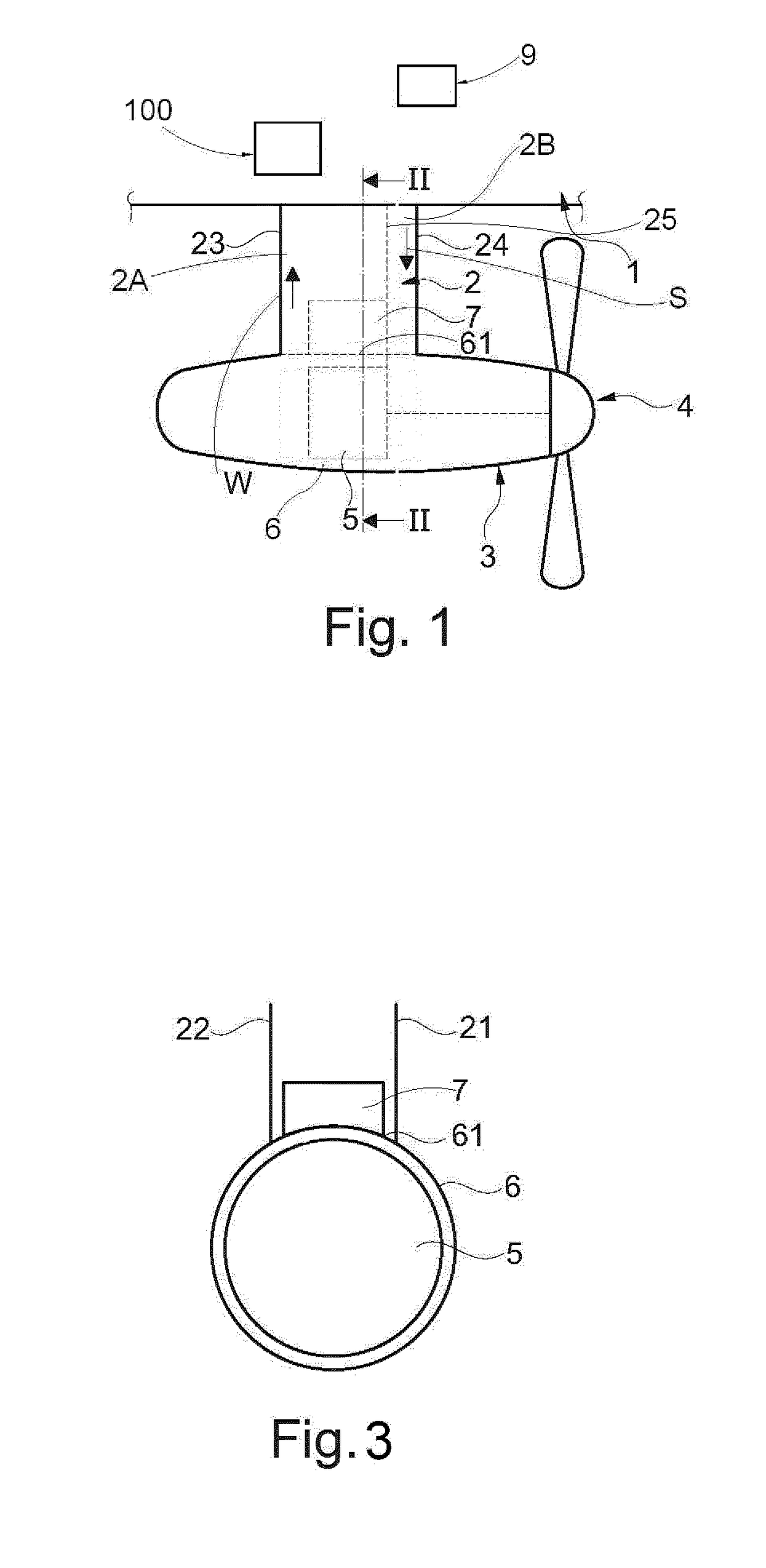
[0023]FIG. 1 illustrates a pod propulsion device according to the present invention. The device comprises a motor casing 3 with a propeller 4 at its front end driven by an electric motor 5. The motor 5 is encapsulated in a motor housing 6 in contact with the circumferential of the motor 5, which motor housing 6 may be an integral part of the casing 3 or a separate part. The motor casing 3 is hanging in a strut 2 through which it is connected to the hull 1 of a ship such that the motor casing is located in water. The propeller 4 drives the ship. The pod propulsion device may be rotatable around a vertical axis (or at least substantially vertical) through the strut 2 for steering the ship. It is to be understood that a propeller may be present also at the rear end of the motor casing 3. The basic principle for pod propulsion of a ship is supposed to be generally known and therefore does not require a detailed description.

[0024]The strut 2 has outer walls enclosing various equipment in...


PUM


Abstract

The invention relates to a system and method for cooling of a pod propulsion device, including a motor casing (3) and a strut (2), which strut (2) is connected at a lower part thereof to the motor casing (3) and is arranged to be connected at an upper part thereof to a hull (1) of a ship, said motor casing (3) including a housing (6) enclosing an electric motor (5) with a stator (51) and a rotor, wherein periodically a forced cooling air flow (W,S) is shifted to use a front duct (2A) as supply (S) for limited time period TF and thereafter shift to use the aft duct (2B) as supply (S) for a limited time period TA. The invention also relates to a ship provided with such a system and method for cooling of pod propulsion device.

Description

FIELD OF INVENTION[0001]The present invention relates to a method for pod propulsion device including a motor casing and a strut, which strut is connected at a lower part thereof to the motor casing and is arranged to be connected at an upper part thereof to a hull of a ship, which motor casing includes a housing enclosing an electric motor with a stator and a rotor, and which housing has an upper portion, regarding the cooling of the stator of the pod propulsion device.[0002]In the present application terms as “upper” and “lower” refers to the normal position of a pod propulsion device when mounted onto a ship. Terms like “axial” refers to the axis of the electric motor in the motor casing. Ship is to be understood as any floating vessel.BACKGROUND OF INVENTION[0003]A pod propulsion device using an electric motor for driving the propeller shaft generates a substantial amount of heat. Since the stator of the motor normally is in contact with the housing of the motor casing a large p...

Claims


Application Information

Patent Timeline
IPC IPC(8): B63H5/125H02K9/10H02K1/20
CPCB63H5/125B63H2005/1258H02K9/10H02K1/20B63H23/24H02K9/227H02K9/225B63H21/17H02K9/20B63H21/38
Inventor LOBELL, ANDERSAHL, DANIEL
Owner KONGSBERG MARITIME SWEDEN AB
Learn More