
Erythrocyte aggregation and leukocyte isolation

Active Publication Date: 2017-06-01
GENERAL ELECTRIC CO
View PDF9 Cites 1 Cited by
  • Summary
  • Abstract
  • Description
  • Claims
  • Application Information

AI Technical Summary

Benefits of technology

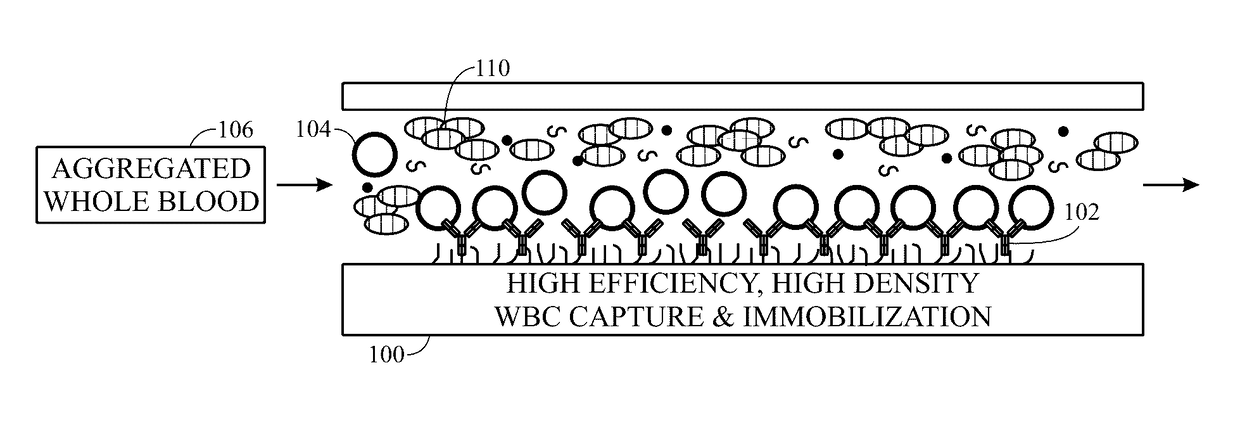
This patent is about a method and device for separating blood components. The device uses a microfluidic chamber with a solution of high-molecular weight polysaccharide to aggregate red blood cells and separate them from other blood components. The device can also include channels for capturing specific white blood cells and coating them with antibodies to bind to specific cells of interest. The technical effects are improved efficiency and accuracy in blood component separation for research and medical applications.

Problems solved by technology

Other common methods include red blood cell (RBC) lysis and red blood cell aggregation in a dextran solution, but separation performance is not as good.
Ficoll-Paque density separation is one such technique, but requires laboratory equipment (a centrifuge),a skilled operator to identify and remove the desired cell layer, and has a lower limit on blood volume due to the increasing difficulty in locating and removing the cell layer as it shrinks in size.
This technique also requires a centrifuge (and therefore, a laboratory) for re-concentration of the diluted cells, and it can damage the leukocytes as well.
In such devices, the pillar size and spacing must be small (˜20-40 μm) and well controlled, making reliable fabrication of these devices a costly endeavor.
Cross-flow separations use small side channels for erythrocyte removal by size and / or deformation, but also require small device dimensions that bring associated cost and reliability concerns (such as potential for device clogging).
Hydrodynamic techniques also exist, but generally these are high-flow approaches that may not perform well for a small volume sample (e.g., less than or equal to 100 μl), and often involve sample dilution or high flow velocities that may damage cells.

Method used


Image

  • Erythrocyte aggregation and leukocyte isolation
  • Erythrocyte aggregation and leukocyte isolation
  • Erythrocyte aggregation and leukocyte isolation

Examples


Embodiment Construction

[0024]One or more specific embodiments will be described below. In an effort to provide a concise description of these embodiments, all features of an actual implementation may not be described in the specification. It should be appreciated that in the development of any such actual implementation, as in any engineering or design project, numerous implementation-specific decisions must be made to achieve the developers' specific goals, such as compliance with system-related and business-related constraints, which may vary from one implementation to another. Moreover, it should be appreciated that such a development effort might be complex and time consuming, but would nevertheless be a routine undertaking of design, fabrication, and manufacture for those of ordinary skill having the benefit of this disclosure.

[0025]When introducing elements of various embodiments of the present invention, the articles “a,”“an,”“the,” and “said” are intended to mean that there are one or more of the ...


PUM


Abstract

A device and / or methodology are described that include a mechanism for separating erythrocytes from other constituents of blood and for purifying leukocytes from blood. The separation and purification aspects may be provided in separate components or within the same component. The separation aspect assists in separating erythrocytes (red blood cells) from other cells in blood, such as by aggregation of the red blood cells. A suitable aggregation device or device component uses chambers with at least one small dimension (e.g., a microfluidic chip) to control the interaction of the blood with a solution containing a high molecular weight polymer (e.g., dextran) to achieve separation.

Description

STATEMENT REGARDING FEDERALLY SPONSORED RESEARCH & DEVELOPMENT[0001]This invention was made with Government support under contract number HDTRA1-12-C-0098 awarded by DTRA. The Government has certain rights in the invention.BACKGROUND[0002]The subject matter disclosed herein relates to erythrocyte aggregation and leukocyte isolation.[0003]In various research and medical contexts, it may be desirable to separate or isolate certain components of an initial composition into one or more purified and / or separated constituents. By way of example, whole blood is a complex composition having various molecular and cellular constituents. In various contexts, it may be desirable to isolate or separate one or more of the whole blood constituents, such as for research purposes, for diagnostic purposes, or as a precursor or step in a medical treatment or preparation of a medically useful composition. The most common way to separate blood components involves the use of a density gradient media and ...

Claims


Application Information

Patent Timeline
IPC IPC(8): G01N33/50C12Q1/24B01L3/00
CPCG01N33/5002B01L3/502769B01L3/502761B01L2300/16B01L3/502738C12Q1/24B01L2200/0647B01L3/502715C12N5/0634C12N5/0641C12N2509/00G01N33/491B01D2313/18G01N2001/4088
Inventor KARP, JESSICA GODINCHEN, XIAOHUISHAIKH, KASHAN ALIWANG, MENGLILENIGK, RALFSURRETTE, CHRISTINE LYNNE
Owner GENERAL ELECTRIC CO
Learn More