
High-pressure tolerant integrated leakage-proof sleeve compensator

Active Publication Date: 2017-06-01
JIANGSU BT PIPE CO LTD
View PDF0 Cites 0 Cited by
  • Summary
  • Abstract
  • Description
  • Claims
  • Application Information

AI Technical Summary

Benefits of technology

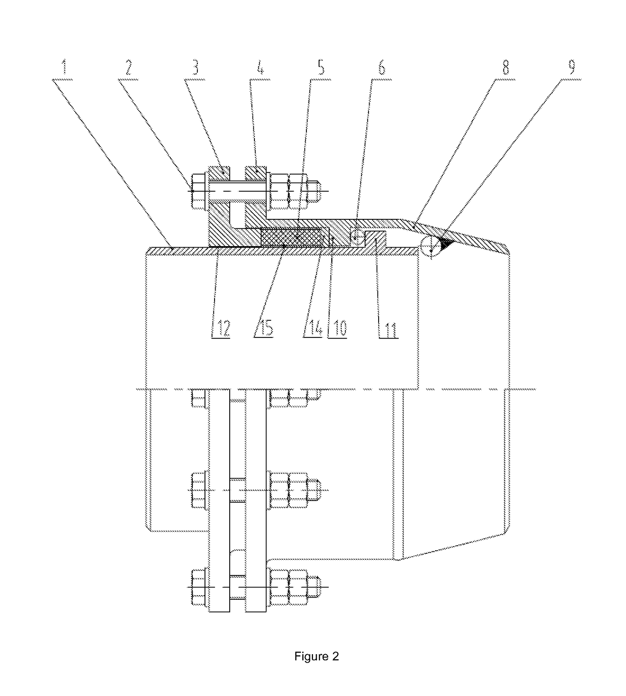
The present invention is a rotary compensator designed to improve sealing performance and prevent leaks and ruptures during use. One technical solution is to add an end seal between the annular outer and inner bosses to reduce gaps and gaps caused by wear. Another solution is to provide a stuffing filling device to the outer sleeve to prevent gaps from affecting the sealing performance of the whole rotary compensator. Additionally, the invention includes wear-resistant carbon fiber layers between the gland packing and the inner pipe to prevent wear of the gland packing and enhance sealing performance. The impact plate is also designed to prevent media from impacting the gland packing and further improve sealing performance. These technical solutions improve the quality, safety, and performance of the rotary compensator.

Problems solved by technology

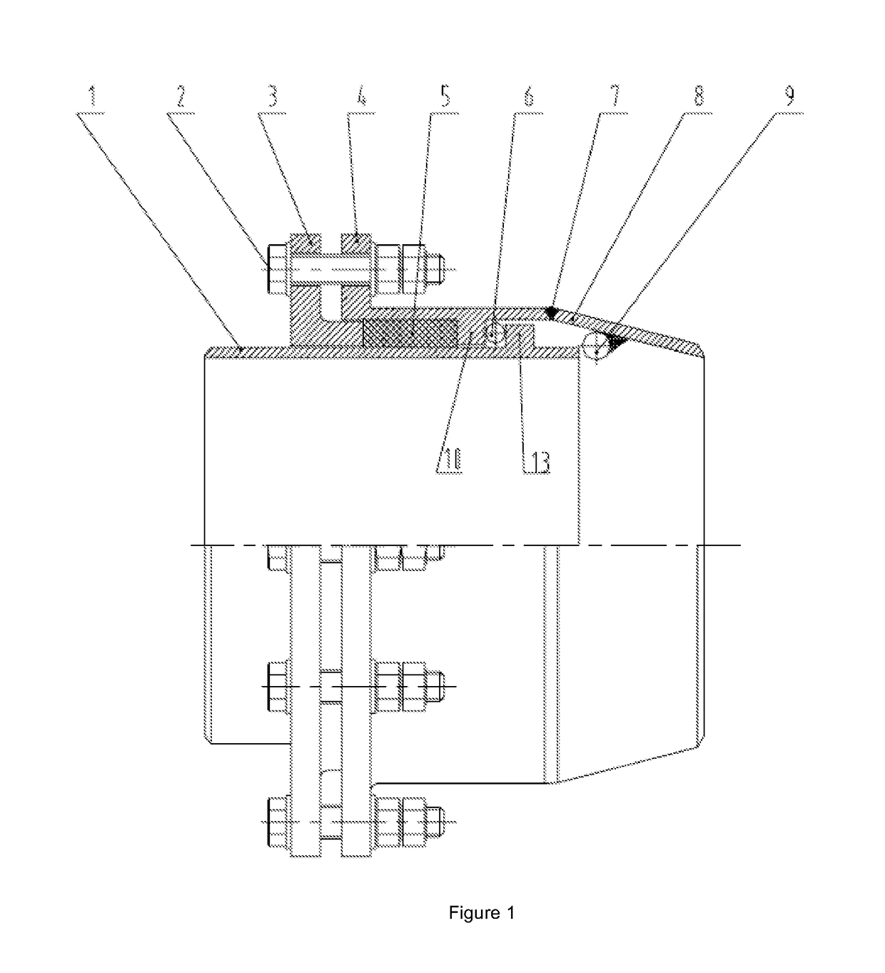
Through study, the applicant found that such butt-welding mode inevitably results in partial overlapping of an annular weld, between an outer sleeve and the connecting pipe, with an inner pipe, and it is difficult to accurately detect the welding quality by means of non-destructive detection using X rays, etc., thus there is no guarantee for the weld quality.
During long-time use, the gland packing between the outer sleeve and the inner pipe has losses (more obvious when the delivered media are high-temperature and high-pressure media) after the long-term impact by the delivered media, resulting in a decline in the sealing effect or malfunction, thus affecting the sealing performance of the whole rotary compensator.
During long-time use, the gland packing between the outer sleeve and the inner pipe has losses (more obvious when the delivered media are high-temperature and high-pressure media) due to the relative rotation of the outer sleeve and the inner pipe, resulting in a decline in the sealing effect or malfunction, thus affecting the sealing performance of the whole rotary compensator.

Method used


Image

  • High-pressure tolerant integrated leakage-proof sleeve compensator
  • High-pressure tolerant integrated leakage-proof sleeve compensator
  • High-pressure tolerant integrated leakage-proof sleeve compensator

Examples


embodiment 1

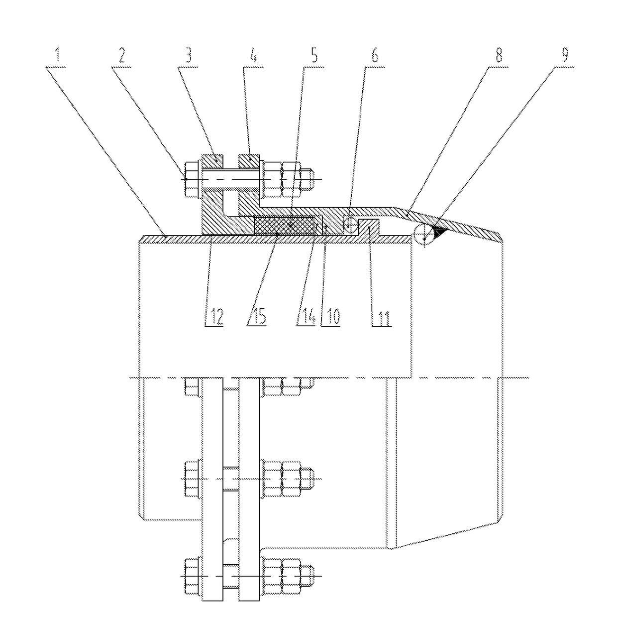
[0031]As shown in FIG. 2, a high-pressure resistant integrated leak-free rotary compensator of this embodiment includes an inner pipe 1, an outer sleeve 4, a connecting pipe 8 and a filler flange 3. The outer sleeve 4 is sleeved on the inner pipe 1. One end of the inner pipe 1 passes through the outer sleeve 4 and is inserted into the connecting pipe 8. The connecting pipe 8 is a reducer pipe, and integrally molded with the outer sleeve 4 to form an integrated structure. The filler flange 3 is sleeved on the inner pipe 1, with one end extending into the outer sleeve 4. The outer sleeve 4 is provided with an annular inner boss 10 on the inner surface. Gland packing 5 is disposed between the annular inner boss 10 and one end of the filler flange 3 extending into the outer sleeve. An impact plate 14 is disposed between the gland packing 5 and the annular inner boss 10 on the inner surface of the outer sleeve. Wear-resistant carbon fiber layers 15 are respectively disposed between the g...

embodiment 2

[0035]As shown in FIG. 3, a high-pressure resistant integrated leak-free rotary compensator of this embodiment includes an inner pipe 1, an outer sleeve 4, a connecting pipe 8 and a filler flange 3. The outer sleeve 4 is sleeved on the inner pipe 1. One end of the inner pipe 1 passes through the outer sleeve 4 and is inserted into the connecting pipe 8. The connecting pipe 8 is a reducer pipe, and integrally molded with the outer sleeve 4 to form an integrated structure. The filler flange 3 is sleeved on the inner pipe 1, with one end extending into the outer sleeve 4. The outer sleeve 4 is provided with an annular inner boss 10 on the inner surface. Gland packing 5 is disposed between the annular inner boss 10 and one end of the filler flange 3 extending into the outer sleeve. An impact plate 14 is disposed between the gland packing 5 and the annular inner boss 10 on the inner surface of the outer sleeve. Wear-resistant carbon fiber layers 15 are respectively disposed between the g...

embodiment 3

[0039]As shown in FIG. 4, a high-pressure resistant integrated leak-free rotary compensator of this embodiment includes an inner pipe 1, an outer sleeve 4, a connecting pipe 8 and a filler flange 3. The outer sleeve 4 is sleeved on the inner pipe 1. One end of the inner pipe 1 passes through the outer sleeve 4 and is inserted into the connecting pipe 8. The connecting pipe 8 is a reducer pipe, and integrally molded with the outer sleeve 4 to form an integrated structure. The filler flange 3 is sleeved on the inner pipe 1, with one end extending into the outer sleeve 4. The outer sleeve 4 is provided with an annular inner boss 10 on the inner surface. Gland packing 5 is disposed between the annular inner boss 10 and one end of the filler flange 3 extending into the outer sleeve. An impact plate 14 is disposed between the gland packing 5 and the annular inner boss 10 on the inner surface of the outer sleeve. Wear-resistant carbon fiber layers 15 are respectively disposed between the g...


PUM


Abstract

The present invention relates to a high-pressure-resistant integrated leakage-free rotating compensator, comprising an inner pipe, an outer sleeve, a connecting pipe and a filler flange. The outer sleeve is arranged on the inner pipe in a sleeved mode. One end of the inner pipe is inserted into the connecting pipe through the outer sleeve. The filler flange is arranged on the inner pipe in a sleeved mode. One end of the filler flange extends into the outer sleeve. An annular inner boss is arranged on the inner surface of the outer sleeve. The portion between the annular inner boss and the end, extending into the outer sleeve, of the filler flange is arranged on gland packing. The outer sleeve and the connecting pipe are of an integrally-formed integrated structure. An anti-impact plate is arranged between the gland packing and the annular inner boss. An abrasion-resistant carbon fiber layer is arranged between the gland packing and the outer surface of the inner pipe. An abrasion-resistant carbon fiber layer is arranged between the gland packing and the inner surface of the outer sleeve. The present invention thoroughly solves the problems that the weld joint flaw inspection is difficult to be performed and even can not be detected due to an existing welding method. Meanwhile, the loss of the sealing material can be effectively reduced by arranging the abrasion-resistant carbon fiber layers and the anti-impact plate, so that the sealing performance of the whole rotating compensator is improved.

Description

BACKGROUND[0001]Technical Field of the Invention[0002]The present invention relates to a high-pressure resistant integrated leak-free rotary compensator.[0003]Description of the Related Art[0004]Pipes used in the electric, petroleum, chemical and thermal power industries, etc. usually need to be equipped with compensation devices. Existing compensation devices include rotary compensators, ripple compensators, sleeve compensators, spherical compensators, etc., which are used for compensating for the axial and radial displacement of pipes. When high-temperature and high-pressure media are delivered in the pipes, high requirements are imposed on rotary compensators, including sufficient displacement compensation, good sealing performance and longer service life.[0005]An outer sleeve and a connecting pipe of an existing rotary compensator are butt-jointed by welding (see FIG. 1), for example Chinese patents 98227061.5, 02258709.8, 200620077450.1, 201120064777.6, 201110163209.6 and 20101...

Claims


Application Information

Patent Timeline
IPC IPC(8): F16L27/08F16L57/06F16L51/00
CPCF16L27/0824F16L57/06F16L51/00F16L27/08F16L27/0812F16L21/04
Inventor HONG, LEIHONG, LIANGZHU, AICHUNCAO, GUANGJINYIN, MINGHUA
Owner JIANGSU BT PIPE CO LTD
Learn More