Multi-aperture camera system using disparity

a camera system and disparity technology, applied in the field of multi-aperture camera systems, can solve the problems of scaling down the camera module, and insufficient general dfd technology to precisely calculate the distance between the image sensor and the obj

Active Publication Date: 2017-05-25
DEXELION INC
View PDF6 Cites 8 Cited by
  • Summary
  • Abstract
  • Description
  • Claims
  • Application Information

AI Technical Summary

Benefits of technology

[0007]Aspects of the present disclosure are to address at least the above-mentioned problems and / or disadvantages involved in the DFD technology and the disparity-based technology and to provide at least the advantages described below. Accordingly, embodiments of the present disclosure are to provide a multi-aperture camera system, and an operating method thereof, for determining a distance between an object and an image sensor, using a plurality of apertures which are formed on a unitary optical system and are offset in at least one of horizontal, vertical or oblique directions of the image sensor to have different centers each other.

Problems solved by technology

However, such general DFD technology is insufficient to exactly calculate a distance between an image sensor and an object because the distance between the image sensor and the object is estimated based on a blurring rate after blurring images and equalizing blur sizes of the images.
With the disparity-based technology requiring two optical systems, it may be inadequate for a scaling-down camera module and may be costly in fabrication.

Method used


Image

  • Multi-aperture camera system using disparity
  • Multi-aperture camera system using disparity
  • Multi-aperture camera system using disparity

Examples


Embodiment Construction

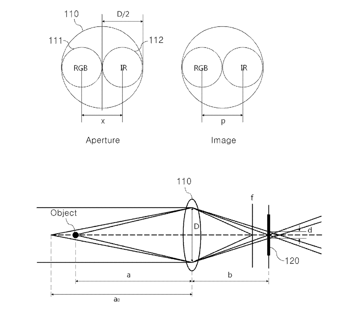
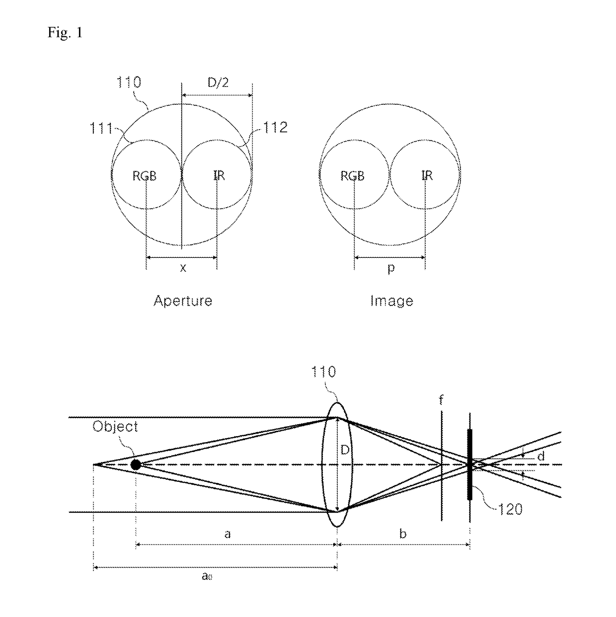
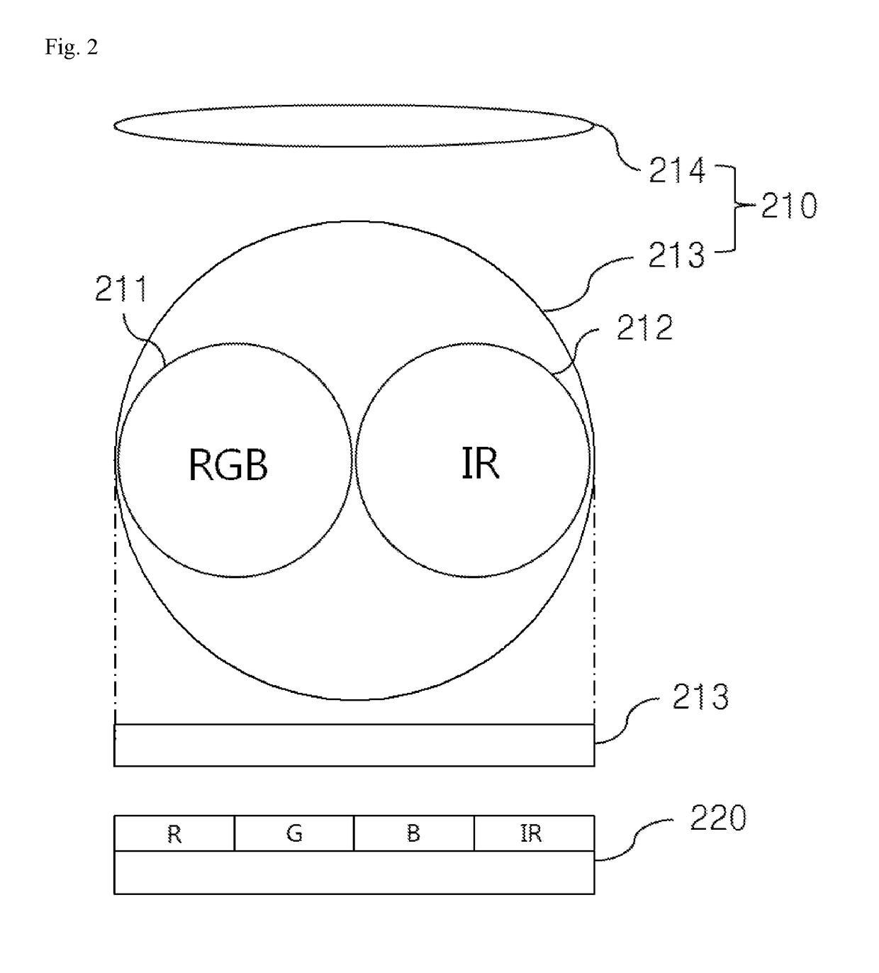
[0053]Hereinafter, various embodiments of the present disclosure will be described in conjunction with the accompanying drawings. Various embodiments described herein, however, may not be intentionally confined in specific embodiments, but should be construed as including diverse modifications, equivalents, and / or alternatives. With respect to the descriptions of the drawings, like reference numerals refer to like elements. FIG. 3 illustrates a first aperture and a second aperture according to an embodiment of the present disclosure.

[0054]The terms used in this specification are just used to describe various embodiments of the present disclosure and may not be intended to limit the scope of the present disclosure. The terms of a singular form may include plural forms unless otherwise specified. Unless otherwise defined herein, all the terms used herein, which include technical or scientific terms, may have the same meaning that is generally understood by a person skilled in the art....


PUM


Abstract

A multi-aperture camera system includes a first aperture introducing an RGB optical signal, a second aperture distinguished from the first aperture and introducing an optical signal, which is different from the RGB optical signal in wavelength, an image sensor processing the RGB optical signal, which is introduced through the first aperture, and obtaining a first image to an object and configured to process an optical signal, which is introduced through the second aperture and is different from the RGB optical signal in wavelength, and obtaining a second image for the object, and a distance determining part using a disparity between the first image and the second image and determining a distance between the image sensor and the object. The first aperture and the second aperture are formed on a unitary optical system to have different centers each other.

Description

CROSS-REFERENCE TO RELATED APPLICATION(S)[0001]This application claims the benefit under 35 U.S.C. §119(a) of a Korean patent application No. 10-2015-0164214 filed Nov. 23, 2015 in the Korean Intellectual Property Office, a Korean patent application No. 10-2016-0012382 filed on Feb. 1, 2016 in the Korean Intellectual Property Office, the entire disclosure of which are hereby incorporated by reference.TECHNICAL FIELD[0002]The present disclosure relates to a multi-aperture camera system using a disparity and more particularly, to technology for determining a distance between an object and an image sensor included in a multi-aperture camera system using a disparity between images which are obtained through a plurality of apertures.BACKGROUND[0003]Depth-From-Defocus (DFD) technology determining a distance between an object and an image sensor operates to estimate a distance between the object and the image sensor using a blur size at each of images obtained through a plurality of apertu...

Claims


Application Information

Patent Timeline
Patent Type & Authority Applications(United States)
IPC IPC(8): H04N5/225H04N5/232G03B9/02H04N9/04
CPCH04N5/2254H04N9/04G03B9/02H04N5/23212H04N5/2253H04N23/66H04N23/75H04N23/125H04N25/131H04N5/2226G03B11/00G03B13/36H04N23/11H04N23/10H04N23/54
Inventor KYUNG, CHONG MINMUN, JUN HO
Owner DEXELION INC
Why Eureka
Try Eureka