Printing apparatus and transmission cable

Active Publication Date: 2017-05-04
SEIKO EPSON CORP
View PDF8 Cites 4 Cited by
  • Summary
  • Abstract
  • Description
  • Claims
  • Application Information

AI Technical Summary

Benefits of technology

The invention is a printing apparatus that generates voltage signals and uses them to eject liquid ink onto a surface. The apparatus includes a circuit that generates voltage signals, transmission cables, and a liquid ejection head. The voltage signals are transmitted by the cables, which includes two tubular conductors and an insulator between them. The liquid ejection head includes piezoelectric elements that selectively receive one of the voltage signals to cause ink ejection. By reducing distortion in the voltage signals, high printing quality can be achieved. The apparatus also includes a voltage supply unit that selectively supplies one or both of the voltage signals to the piezoelectric elements, improving printing quality. Overall, the invention simplifies the process of generating and transmitting voltages to the liquid ejection head, resulting in improved printing quality.

Problems solved by technology

This is because, with the distortions of the transmitted voltage signals, the piezoelectric elements are not properly deformed (contracted and / or elongated), thereby causing the amount of liquid ejected by the deformation of each of the piezoelectric elements to be varied, and as a result, a situation in which correct sizes of dots are not formed on the paper and this formation of incorrect sizes of dots degrades the printing quality may occur.
Thus, in the transmission cables whose lengths have become large, the values of inductance elements and resistance elements of the conductors increase, and as a result, a situation in which distortions are more likely to arise in the voltage signals transmitted in the transmission cables occurs.
As a result, with the increase of the number of the conductors, for example, the flexible flat cables become hard to bend, and this may interfere with the movement of the carriage.
Such coaxial cables, however, have a higher rigidity and are harder to bend, as compared with the flexible flat cables.
Thus, in such a printer configured to allow a carriage that reciprocates to include a liquid ejection head, when the number of the coaxial cables is increased, that is, when the number of conductors constituting the coaxial cables is increased, for example, a situation in which the coaxial cables, in which the number of the conductors is increased, interfere with the movement of the carriage may occur.

Method used


Image

  • Printing apparatus and transmission cable
  • Printing apparatus and transmission cable
  • Printing apparatus and transmission cable

Examples


Embodiment Construction

[0040]Hereinafter, an embodiment of the printing apparatus will be described with reference to the drawings.

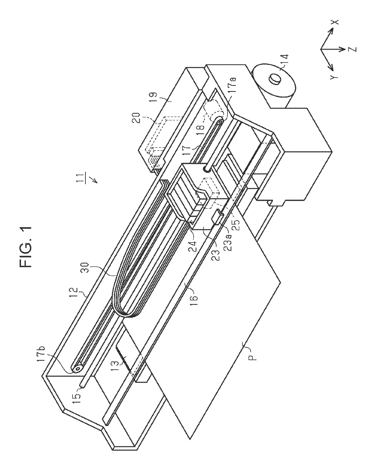
[0041]As shown in FIG. 1, a printing apparatus 11 is an ink jet printer that allows a liquid ejection head 25 to eject inks, each of which is an example of a liquid, onto paper P, which is an example of a medium, to execute printing processing (recording processing). In this embodiment, when the printing processing is executed, the paper P is transported in one direction, and is subjected to a printing process at a position facing the liquid ejection head 25. This direction in which the paper P is transported will be hereinafter referred to as a transport direction Y, and a direction perpendicular to the direction Y and along the width direction of the paper P will be hereinafter referred to as a scan direction X. That is, the scan direction X and the transport direction Y are directions intersecting with each other (preferably, perpendicular to each other), and, in this embod...


PUM


Abstract

A printing apparatus including a voltage signal generation circuit configured to generate a plurality of voltage signals including a first voltage signal and a second voltage signal; and at least one transmission cable configured to transmit the plurality of voltage signals, the transmission cable including a first tubular conductor including a hollow core and configured to transmit the first voltage signal, a second tubular conductor disposed over an outer circumference of the first tubular conductor with a first insulator between the outer circumference of the first tubular conductor and an inner circumference of the second tubular conductor and being in a constant-voltage applied state, and a third tubular conductor disposed over an outer circumference of the second tubular conductor with a second insulator between the outer circumference of the second tubular conductor and an inner circumference of the third tubular conductor and configured to transmit the second voltage signal.

Description

[0001]The entire disclosure of Japanese Patent Application No. 2015-212866, filed Oct. 29, 2015 is expressly incorporated by reference herein.BACKGROUND[0002]1. Technical Field[0003]The present invention relates to a printing apparatus provided with transmission cables for transmitting voltage signals to a liquid ejection head, and to the transmission cables.[0004]2. Related Art[0005]Among printers, each being an example of a printing apparatus, there is a printer including a liquid ejection head, a voltage signal generation circuit, and transmission cables and configured such that voltage signals generated by the voltage signal generation circuit are transmitted to the liquid ejection head using the transmission cables, and then are supplied to a plurality of piezoelectric elements included in the liquid ejection head to allow the liquid ejection head to eject liquids so as to allow characters and / or images to be printed on paper or any other printing medium.[0006]In such a printer...

Claims


Application Information

Patent Timeline
IPC IPC(8): B41J2/045
CPCB41J2002/14491B41J2/04581
Inventor KONDO, YOICHIRO
Owner SEIKO EPSON CORP
Why Eureka
Try Eureka