
Charged particle beam therapy and magnetic resonance imaging

a charge particle and beam technology, applied in the field of charge particle beam therapy and magnetic resonance imaging, can solve the problems of severe problems, significant deviation of the dose delivered from the original dose plan, and difficulty in real-time magnetic resonance imaging (mri) during the delivery of the charged particle beam, so as to improve the treatment of particle beams and improve the effect of magnetic resonance imaging and reliable magnetic resonance imaging

Active Publication Date: 2017-05-04
KONINKLJIJKE PHILIPS NV
View PDF7 Cites 14 Cited by
  • Summary
  • Abstract
  • Description
  • Claims
  • Application Information

AI Technical Summary

Benefits of technology

The invention aims to improve magnetic resonance imaging (MRI) during particle beam treatment. It provides a system for acquiring MRI data and a particle beam line for directing particles to an irradiation volume within the MRI system. An improved shielding method compensates for magnetic field distortion, ensuring accurate particle beam guidance. This invention allows for reliable and effective MRI imaging during particle beam treatment.

Problems solved by technology

However, even small movements of the subject of interest, e.g. of anatomical structures in the path of the beam or a displacement of the target zone, can lead to significant deviations of the delivered dose from the original dose plan.
For charged particle beam therapy, real-time magnetic resonance imaging (MRI) during the delivery of the charged particle beam is challenging because of the strong magnetic fields associated with MRI and strong magnetic fields used for directing the particle beam to the target zone.
Hence, superposition of and interaction between the magnetic fields may cause severe problems, in particular for MRI.
This field will cause image distortion and other artifacts.
A static compensation of the PT field at the MRI system, e.g. using shimming, is not feasible because of the rotation of the bending magnets about the z-axis of the MRI system.

Method used


Image

  • Charged particle beam therapy and magnetic resonance imaging
  • Charged particle beam therapy and magnetic resonance imaging
  • Charged particle beam therapy and magnetic resonance imaging

Examples


Embodiment Construction

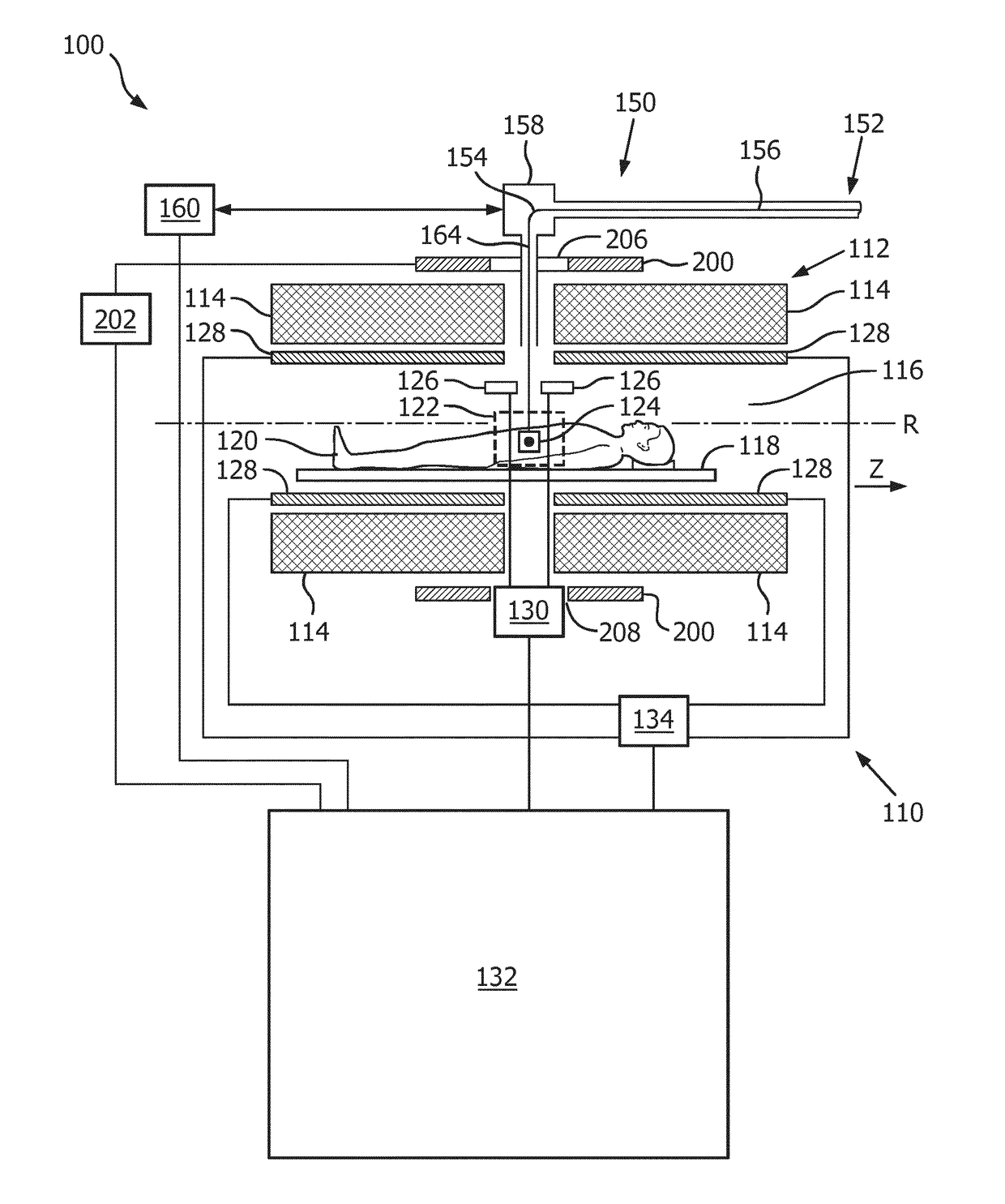
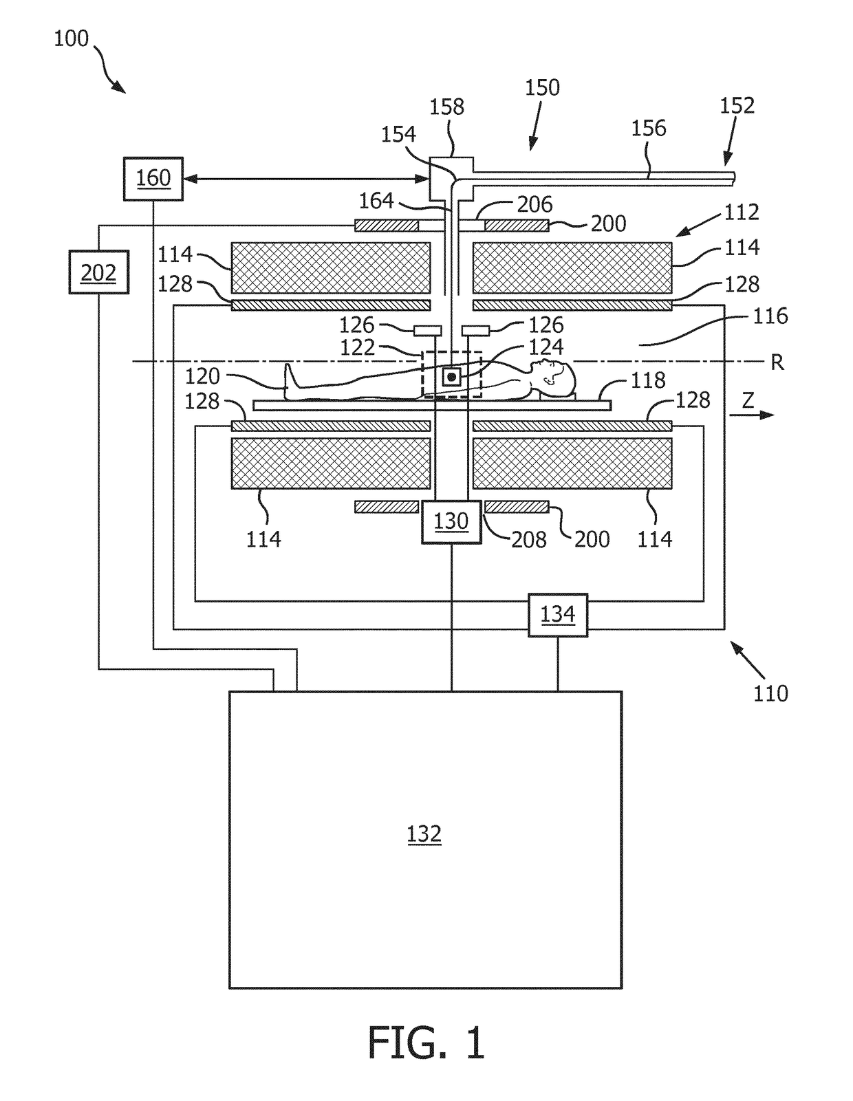
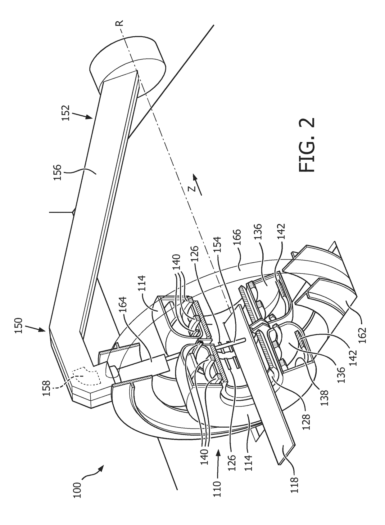
[0051]FIGS. 1 and 2 show a medical apparatus 100 according to a preferred embodiment.

[0052]The medical apparatus 100 comprises a magnetic resonance imaging (MRI) system 110 that comprises a magnetic resonance (MR) magnet 112, also referred to as main magnet, which is provided as split magnet with two submagnets 114. As can be seen in detail in FIG. 2, each sub-magnet 114 comprises a cryogenic chamber 136, which is provided with a radiation shield 138. Within the cryogenic chamber 136 are arranged inner superconducting coils 140 adapted for generating the main magnetic field and an outer superconducting shielding coil 142. The superconducting shielding coil 142 is adapted such that there is a region of zero magnetic field surrounding the sub-magnet 114.

[0053]Within a bore 116 of the sub-magnets 114, there is provided a support 118 adapted for receiving a subject of interest 120. Between the two sub-magnets 114, there is an imaging volume 122 where the magnetic field is uniform enough...


PUM


Abstract

The present invention provides a medical apparatus (100) comprising a magnetic resonance imaging system (110) for acquiring magnetic resonance data from an imaging volume (122) covering at least partially a subject of interest (120), wherein the magnetic resonance imaging system (110) comprises a main magnet (112) for generating a magnetic field within the imaging volume (122), a particle beam apparatus (150) having a particle beam line (152) for a particle beam (154) of charged particles, including a gantry (156) configured for rotating around a rotational axis (R), which is arranged in the longitudinal direction of the main magnet (112), wherein the gantry (156) comprises at least one bending magnet (158) for directing the particle beam (154) to an irradiation volume (124) within the imaging volume (122), an active compensation coil (200), which is arranged to substantially surround at least the imaging volume (122), and a control unit (132) for controlling the active compensation coil (200) for canceling a stray field caused by the at least one bending magnet (158) within the imaging volume (122) at least in the longitudinal direction of the main magnet (112). The present invention also provides a shielding method for use in the above medical apparatus (100).

Description

FIELD OF THE INVENTION[0001]The invention relates to the area of guiding of charged particles to a target zone within a subject of interest, whereby the particles are guided using magnetic resonance imaging.BACKGROUND OF THE INVENTION[0002]In charged particle beam therapy, an energetic charged particle beam is directed at a target zone of a subject. The primary mechanism for interaction of a beam comprising charged particles with matter is through the Coulomb force. The cross section for Coulomb collisions increases as the relative velocity of two particles decreases. As a charged particle beam travels through a subject, it loses energy more and more rapidly. The effect of this is that the majority of the energy of the particle beam is deposited near the end of the beam path. Therefore, a large peak of energy is deposited at the end of the beam path which is called the Bragg peak.[0003]Accordingly, charged particle beam therapy allows very precise delivery of high dose to a target z...

Claims


Application Information

Patent Timeline
Patent Type & Authority Applications(United States)
IPC IPC(8): A61N5/10G01R33/48G01R33/3875A61B5/055G01R33/38
CPCA61N5/1049A61N5/1081A61B5/055A61N2005/1087G01R33/3875G01R33/4808A61N2005/1055G01R33/3806
Inventor OVERWEG, JOHANNES ADRIANUS
Owner KONINKLJIJKE PHILIPS NV
Learn More