
Surroundings detection device for agricultural work machines

a detection device and a technology for agricultural work machines, applied in the direction of guiding agricultural machines, agricultural tools and machines, instruments, etc., can solve the problems of limited sensor to the ground contour, high degree of regulatory effort can be regarded as disadvantageous, and certain imprecisions in automatic control are to be expected, so as to prevent damage to agricultural work machines caused by obstacles, reduce material impact, and improve efficiency

Active Publication Date: 2017-05-04
CLAAS SELBSTFAHRENDE ERNTEMASCHINEN GMBH
View PDF54 Cites 49 Cited by
  • Summary
  • Abstract
  • Description
  • Claims
  • Application Information

AI Technical Summary

Benefits of technology

The patent describes an agricultural work machine that has a device to detect its surroundings. This device can be used to control the machine's working elements, such as the hydraulic steering system and the reel. By scanning the surroundings in specific directions, the machine can automatically adjust its position to the crop edge and adapt to the crop's height. This allows for precise cutting and reduces the need for multiple sensors and increases efficiency. Overall, the patent aims to improve the machine's responsiveness and accuracy in detecting and responding to its surroundings.

Problems solved by technology

The disadvantage here is that the sensor is limited to the ground contour.
It is also disadvantageous that because of the single scanning plane, the controls can only react sluggishly, such that certain imprecisions in the automatic control are to be expected.
The high degree of regulatory effort can be regarded as disadvantageous here, by means of which the detection range must be adjusted to the specific circumstances.
Furthermore, a continuous scanning and mapping of the field is difficult to carry out due to the changing detection range area.
Moreover, when changing the direction, width and range of the detection region, the control and regulating device only has incomplete or imprecise data for controlling working elements.
It is likewise disadvantageous that the surrounding detection device is limited to the crop edge detection.

Method used


Image

  • Surroundings detection device for agricultural work machines
  • Surroundings detection device for agricultural work machines
  • Surroundings detection device for agricultural work machines

Examples


Embodiment Construction

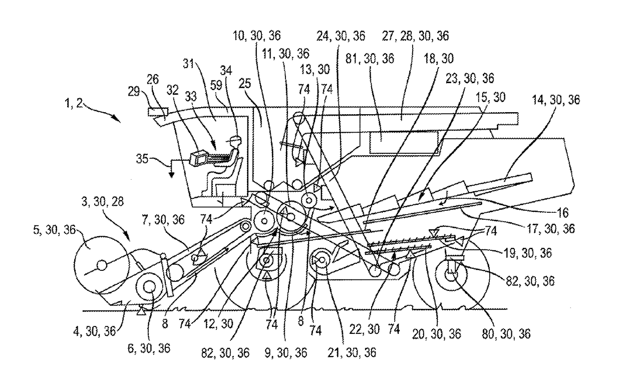
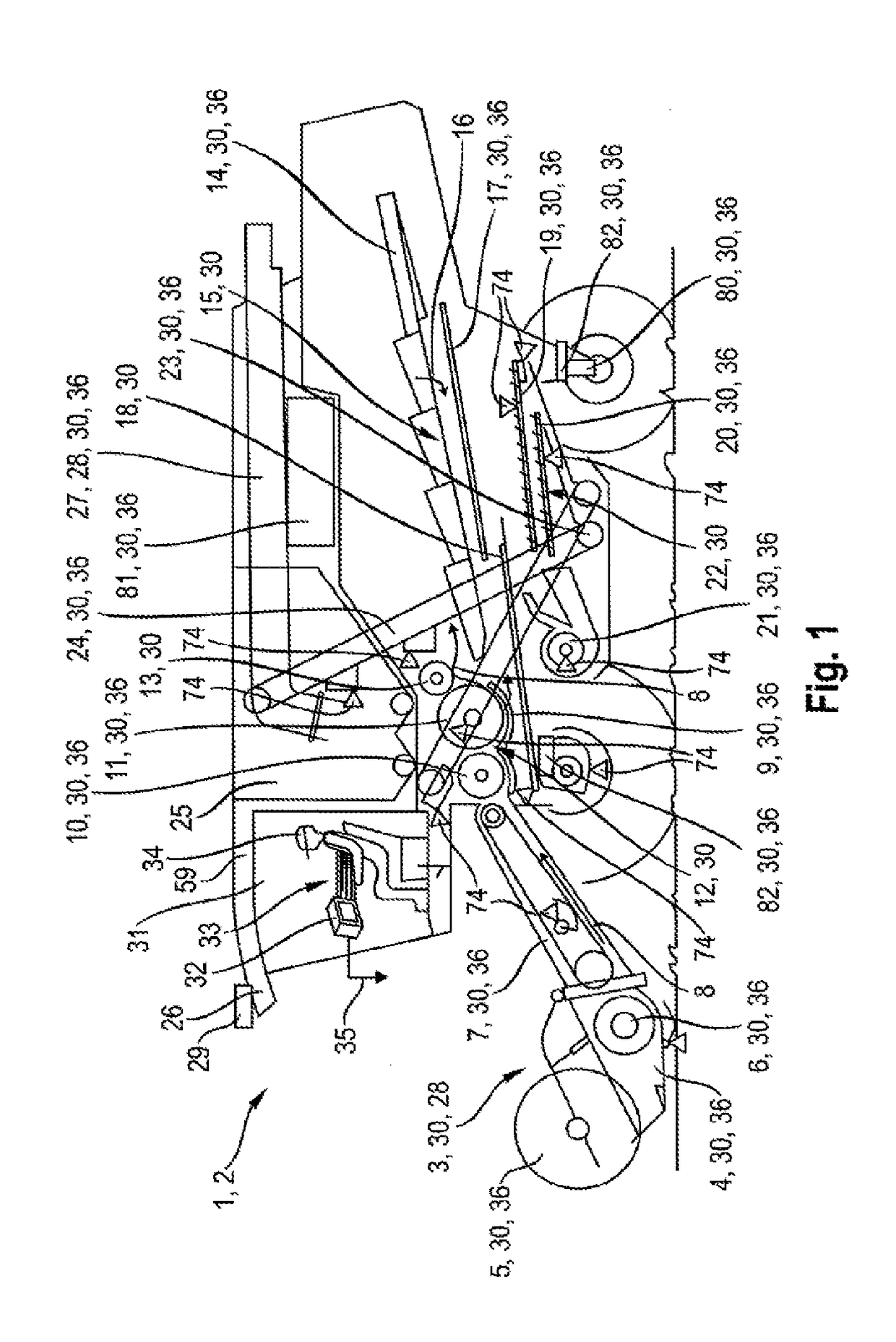
[0034]The agricultural work machine depicted in FIGS. 1 to 4 is a self-driving combine harvester. It is within the scope of the agricultural work machine to also be in the form of another self-driving harvesting machine, including a field chopper, or a system transporter, e.g. a tractor.

[0035]The agricultural work machine 1 schematically depicted in FIG. 1 as a combine harvester, has a cutting unit 3 in its front region, composed of cutter bars 4, the reel 5, and the header auger 6. The cutting unit 3 is connected to the inclined conveyor 7 of the combine harvester 2 in the manner known per se. The plants are cut by the cutter bars 4, and the harvest is fed to the header auger 6 by means of the reel 5. The harvest flow 8 supplied to the inclined conveyor 7 is supplied, in the upper, rear region of the inclined conveyor 7, to the lower accelerating drum 10, at least partially encased by a threshing concave 9, and subsequently to the threshing drum 11, at least partially encased by a ...


PUM


Abstract

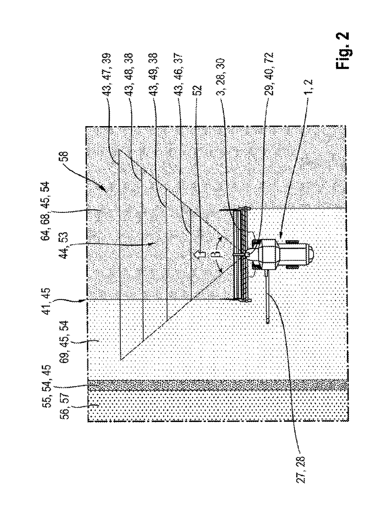
An agricultural work machine is provided comprising a surroundings detection device for detecting a surroundings in sections, and one or more controllable working elements, wherein the surroundings detection device generates surroundings detection signals, which can be processed in a control and regulating device assigned to the agricultural work machine, wherein the surroundings detection device is designed as a scanner, which scans the surroundings in scanning planes, and wherein each scanning plane is assigned to the control of working elements.

Description

CROSS REFERENCE TO RELATED APPLICATION[0001]This application claims priority to German Patent Application No. DE 10 2015 118 767.1, filed Nov. 3, 2015, the entirety of which is hereby incorporated by reference herein.BACKGROUND[0002]This disclosure describes a surroundings detection device included in an agricultural work machine.[0003]In order to relieve the driver of an agricultural work machine (“vehicle”) and increase the efficiency of the agricultural work machine operating on a field, the control of the vehicle, e.g. along a crop edge, and the control of working elements of the vehicle, e.g. the reel height in a combine harvester or the chaff unit performance in a field chopper, is increasingly regulated automatically in today's world based on the surrounding conditions and the expected harvest. For this, agricultural work machines in the prior art are frequently equipped with surroundings detection devices, the surroundings detection signals of which are used for determining ...

Claims


Application Information

Patent Timeline
IPC IPC(8): A01D41/127G01S17/93A01D69/03A01D34/00A01D57/02G01S17/931
CPCA01D41/1274A01D34/006A01D57/02A01D41/1278A01D2101/00G01S17/936A01D34/13A01D34/04A01D69/03A01B69/008A01D41/127G01S17/931
Inventor MIDDELBERG, RENEKRAUSE, THILO
Owner CLAAS SELBSTFAHRENDE ERNTEMASCHINEN GMBH
Learn More