
Support for a conduit

a technology for supporting pipes and conduits, applied in the direction of pipe supports, pipes/joints/fittings, mechanical devices, etc., can solve problems such as wear in these joints, and achieve the effect of limiting the risk of wear to the joints of connectors and avoiding stress

Active Publication Date: 2017-04-20
AIRBUS OPERATIONS (SAS)
View PDF19 Cites 11 Cited by
  • Summary
  • Abstract
  • Description
  • Claims
  • Application Information

AI Technical Summary

Benefits of technology

The patent text is about a way to adjust the position of the axis of a pipe relative to its support, which helps to prevent damage to the pipe connectors and reduce the risk of wear and tear.

Problems solved by technology

This misalignment produces stresses in the region of the joints of the connectors which causes the occurrence of wear in these joints.

Method used


Image

  • Support for a conduit
  • Support for a conduit
  • Support for a conduit

Examples


Embodiment Construction

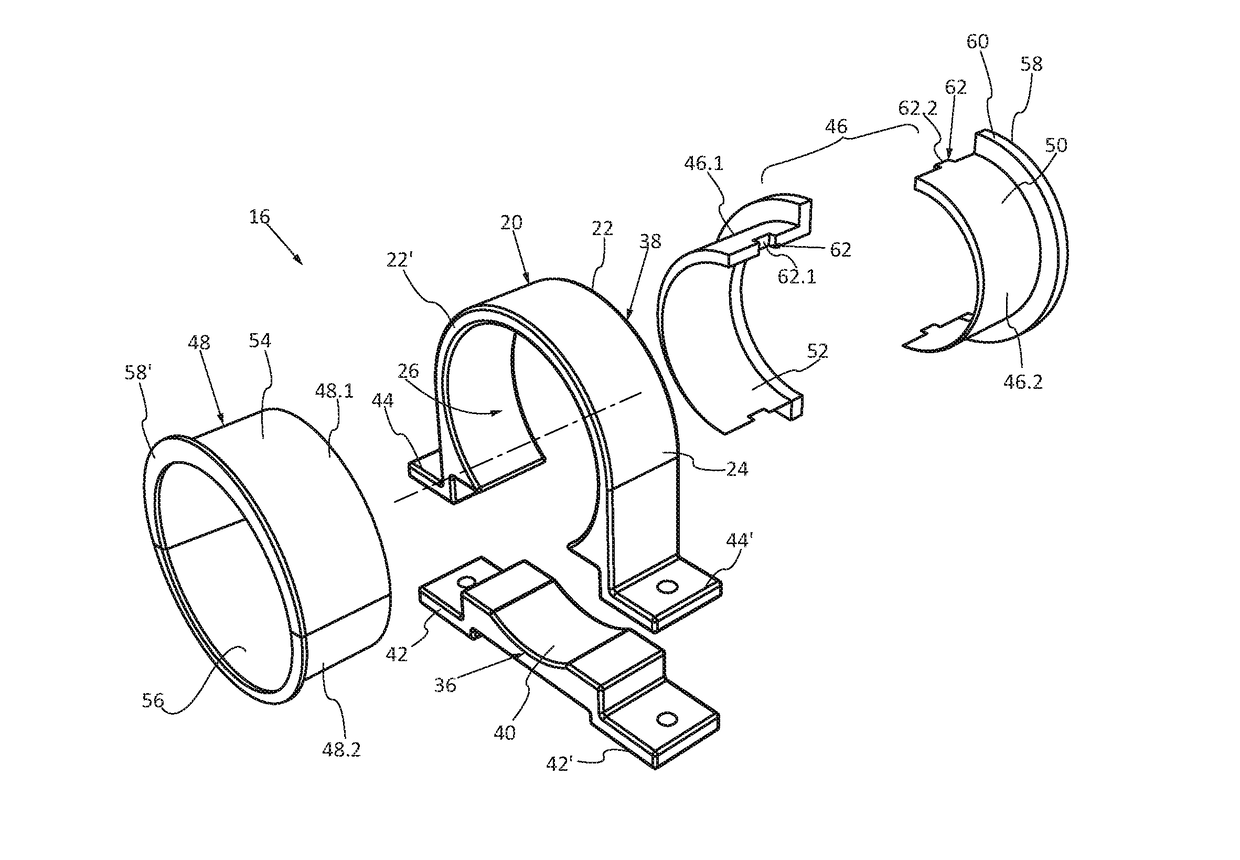
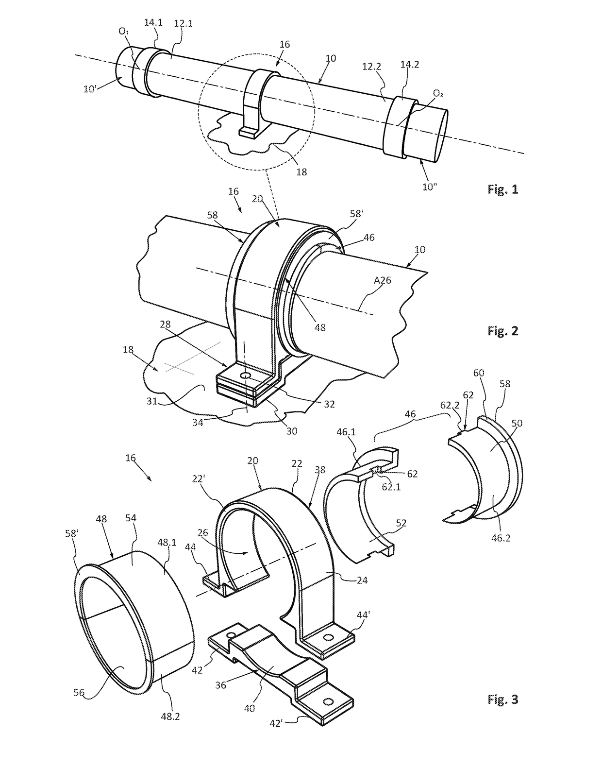
[0032]A part of a fluid circuit which comprises a pipe 10 positioned between an upstream pipe 10′ and a downstream pipe 10″ has been shown in FIG. 1.

[0033]The pipe 10 comprises a first end 12.1 connected to the upstream pipe 10′ by means of a first connector 14.1 and a second end 12.2 connected to the downstream pipe 10″ by means of a second connector 14.2. According to one embodiment, each connector 14.1 and 14.2 comprises a sleeve, the first or second end 12.1, 12.2 of the pipe 10 being fitted therein. To ensure the sealing, each connector 14.1, 14.2 comprises a seal interposed between the end 12.1, 12.2 of the pipe 10 and the sleeve. According to this embodiment, at each of its first and second ends 12.1 and 12.2, the pipe 10 comprises a connection with the first or second connector 14.1, 14.2 which is of the linear type. The linear connections present at the ends of the pipe 10 are illustrated by their centers respectively O1 and O2 in FIG. 1.

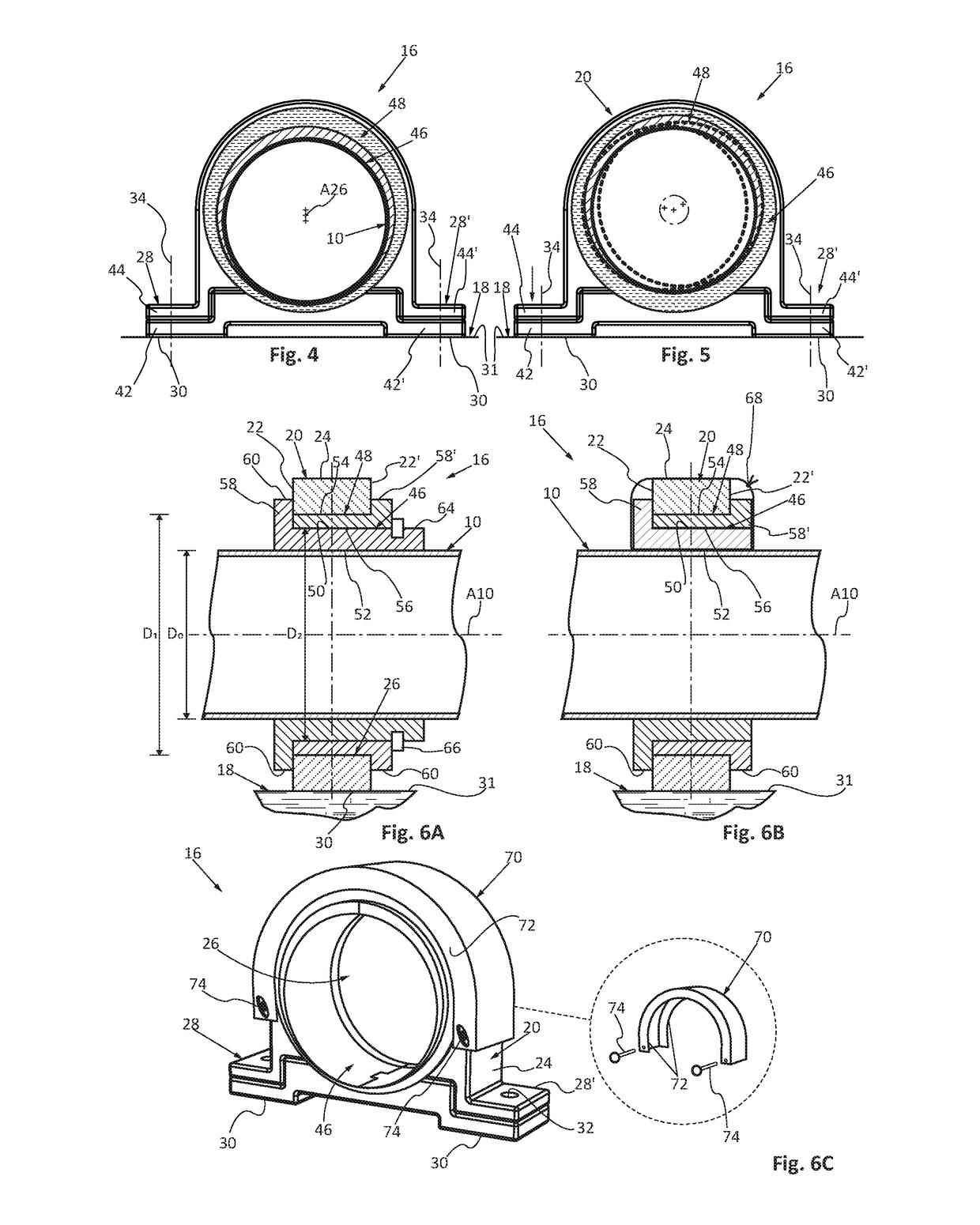
[0034]As illustrated in FIG. 6A, the...


PUM


Abstract

A support for a pipe which comprises a body which comprises a through-orifice for the pipe. The through-orifice has a diameter which is greater than an external diameter of the pipe. At least one base of the support is configured so as to be in contact with and connected to a fixing surface. A first ring and a second ring each have an eccentric orifice and are configured so as to be fitted one into the other in the orifice of the body about the pipe when the support is put in position. By rotating at least one of the first and second rings, the position of the axis of the pipe may be adjusted radially relative to the support.

Description

CROSS-REFERENCES TO RELATED APPLICATIONS[0001]This application claims the benefit of the French patent application No. 1559838 filed on Oct. 16, 2015, the entire disclosures of which are incorporated herein by way of reference.BACKGROUND OF THE INVENTION[0002]The present application relates to a support for a pipe, for example a pipe for a fluid circuit.[0003]An aircraft comprises at least one fluid circuit for channeling the fuel from a tank to the engines.[0004]This fluid circuit comprises, amongst other things, a succession of pipes arranged end-to-end. Two successive pipes are connected by a connector which comprises a sleeve, the ends of the pipes being fitted therein. In order to ensure the sealing, an annular seal is interposed between the end of each pipe and the sleeve of the connector.[0005]According to the known embodiments, the connectors are configured so as to compensate for a possible angular error and to permit a slight axial movement between two successive pipes.[00...

Claims


Application Information

Patent Timeline
Patent Type & Authority Applications(United States)
IPC IPC(8): F16L3/12F16L3/10
CPCF16L3/10F16L3/1207F16L3/1091F16L3/16
Inventor ALQUIER, BRUNORIVERA, CLEMENTMILLET, GERARD
Owner AIRBUS OPERATIONS (SAS)
Learn More