
Method and functional monitoring apparatus for functional monitoring of an apparatus for variable setting of a cylinder compression in a reciprocating-piston internal combustion engine

a technology of internal combustion engine and cylinder compression, which is applied in the direction of machines/engines, electric control, instruments, etc., can solve the problems of affecting the time course of the engine position, compression also affecting the fuel consumption of the internal combustion engine and the exhaust gas emissions, etc., and achieves the effect of enhancing the method accuracy and accurate functional monitoring of the apparatus

Active Publication Date: 2017-04-13
ROBERT BOSCH GMBH
View PDF1 Cites 6 Cited by
  • Summary
  • Abstract
  • Description
  • Claims
  • Application Information

AI Technical Summary

Benefits of technology

The patent describes a method for monitoring the function of an apparatus in an internal combustion engine. The method involves measuring the engine parameter in real-time and comparing it to a reference value. The reference value can be determined based on the expected behavior of the engine under different conditions. By measuring the engine parameter in this way, the method can provide a plausible check on the functionality of the apparatus and can also enable the identification of specific faults in the engine. The method can be used in a simple and efficient way, and it can provide a reliable measure of engine performance during operation.

Problems solved by technology

Variable cylinder compression also influences the fuel consumption of the internal combustion engine and the exhaust gas emissions of the internal combustion engine.
In particular when the drive train of the internal combustion engine is open, and in unfueled coasting mode, elevated return forces in the cylinder of the internal combustion engine at a higher cylinder compression cause greater friction during engine operation and thus a change in the time course of the engine position.

Method used


Image

  • Method and functional monitoring apparatus for functional monitoring of an apparatus for variable setting of a cylinder compression in a reciprocating-piston internal combustion engine
  • Method and functional monitoring apparatus for functional monitoring of an apparatus for variable setting of a cylinder compression in a reciprocating-piston internal combustion engine
  • Method and functional monitoring apparatus for functional monitoring of an apparatus for variable setting of a cylinder compression in a reciprocating-piston internal combustion engine

Examples


Embodiment Construction

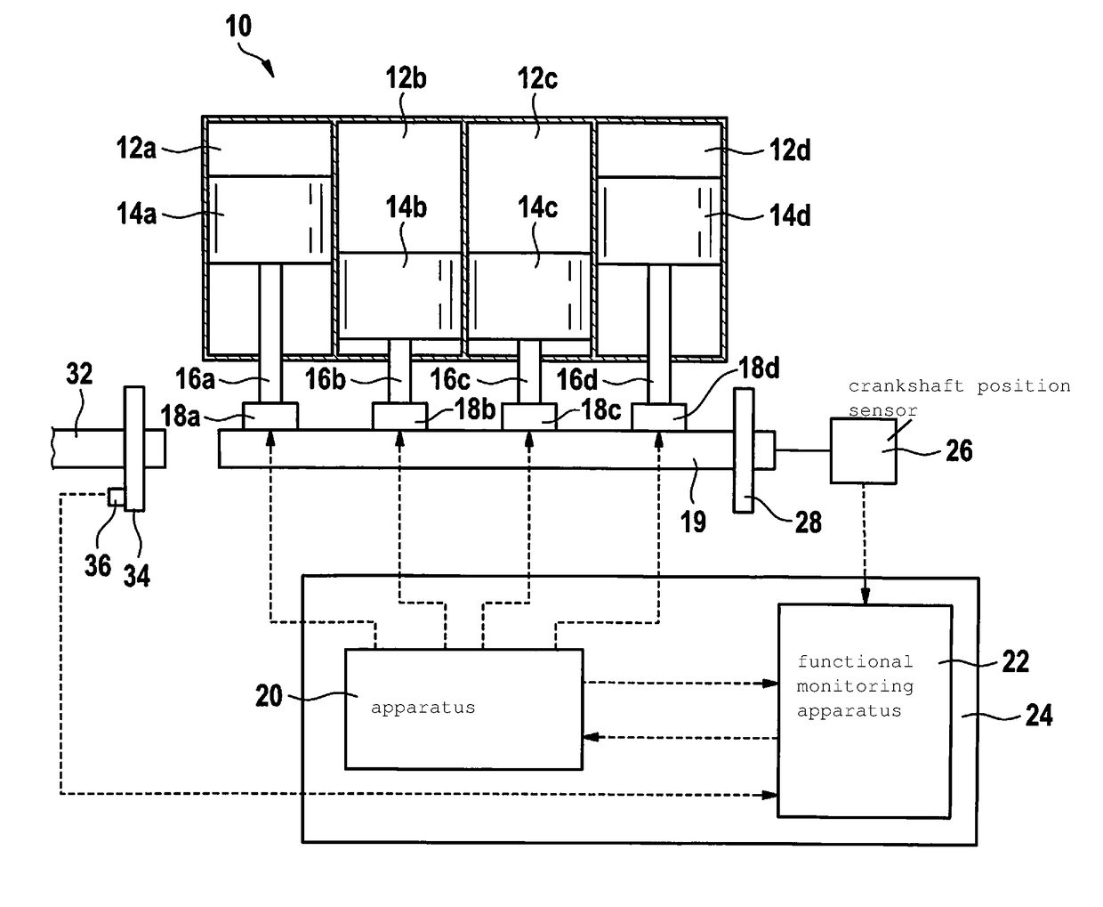
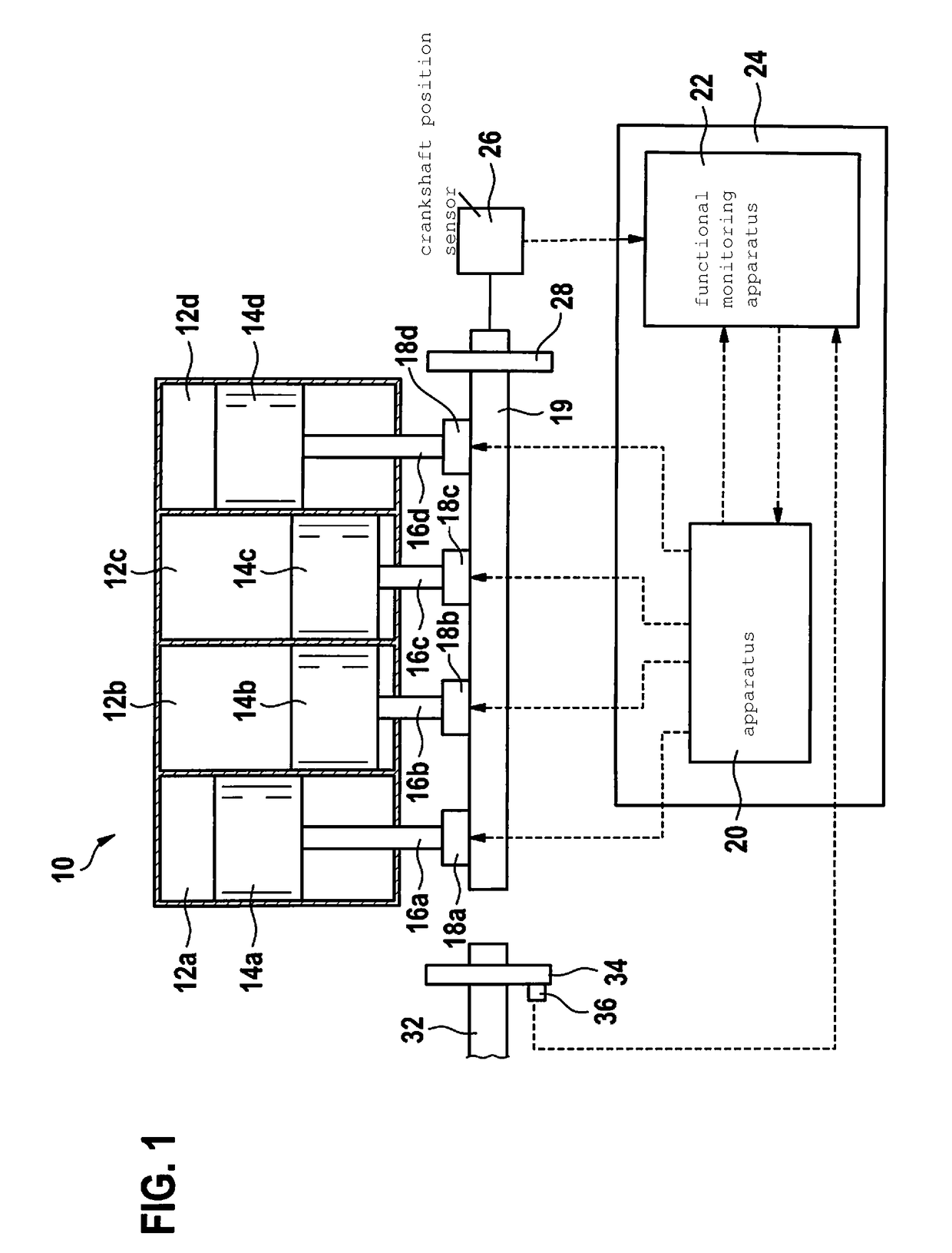
[0028]Internal combustion engine 10 shown in FIG. 1 has four cylinders 12a to 12d whose internal volume can be enlarged and reduced by way of a respective piston 14a to 14d. Each of pistons 14a to 14d is movable with a different connecting rod 16a to 16d, to which control can be applied by way of a different compression setting member 18a to 18d and which are connected to a crankshaft 19 of internal combustion engine 10. Setting members 18a to 18d can have control applied to them individually by way of a shared apparatus 20 for variable setting of a cylinder compression in cylinders 12a to 12d, the correct operation of which can be monitored by a functional monitoring apparatus 22. Apparatus 20 and functional monitoring apparatus 22 are part of an electronic control device 24 for controlling internal combustion engine 10. The cylinder compression is settable in individual-cylinder fashion using conventional techniques, as described for example in DE 197 03 948 C1, by modifying a len...


PUM


Abstract

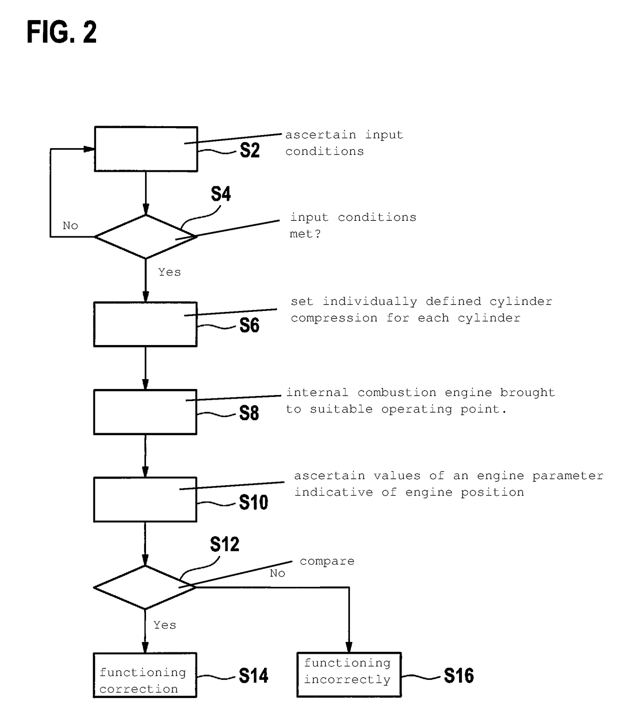
A method for functional monitoring of an apparatus for variable setting of a cylinder compression in a reciprocating-piston internal combustion engine is described, including ascertaining a value of an engine parameter which is indicative of an engine position of the internal combustion engine at a defined cylinder compression; comparing the ascertained value with a further value of the engine parameter; and determining, depending on a result of the comparison, whether the apparatus for variable setting of the cylinder compression is functioning correctly.

Description

CROSS REFERENCE[0001]The present application claims the benefit under 35 U.S.C. §119 of U.S. application Ser. No. 62 / 240356 filed on Oct. 12, 2015, and German Patent Application No. DE 102016200190.6 filed on Jan. 11, 2016, each of which is expressly incorporated herein by reference in its entirety.FIELD[0002]The present invention relates to a method and a functional monitoring apparatus for functional monitoring of an apparatus for variable setting of a cylinder compression in a reciprocating-piston internal combustion engine, to a computer program, and to an electronic storage medium.BACKGROUND INFORMATION[0003]As permitted CO2 exhaust gas emission values in the automotive sector become more stringent, it is desirable to develop new technologies for improving overall efficiency of a reciprocating-piston internal combustion engine. Such technology relates, for example, to variable setting of a cylinder compression of gas in cylinders of the internal combustion engine, in order to a...

Claims


Application Information

Patent Timeline
IPC IPC(8): G01M15/08F02D15/00
CPCG01M15/08G01M99/008F02D15/00F02B77/08F02D41/221F02D15/02F02D41/009F02D41/042F02D41/062F02D41/1497F02D2200/101Y02T10/40F02D35/0015F02D41/1454F02D41/26F02D2200/0802
Inventor GLADEL, PASCALKESCH, BERNDJESSEN, HOLGER
Owner ROBERT BOSCH GMBH
Learn More