
Grinding method

Active Publication Date: 2017-04-06
DISCO CORP
View PDF0 Cites 21 Cited by
  • Summary
  • Abstract
  • Description
  • Claims
  • Application Information

AI Technical Summary

Benefits of technology

The present invention provides a grinding method that reduces the time required for grinding. This is achieved by using a pre-grinding step, where the grinding face of the grindstone is transcribed onto the plate-shaped workpiece. By measuring the thickness of the workpiece, the distance between the grinding face of the grindstone and the upper face of the chuck table is determined indirectly, and the variation in this distance when adjusting the inclination of the chuck table is calculated. The grinding means and inclination adjustment means are operated based on this variation to maintain the contacting state between the grinding object face of the workpiece and the grinding face. This allows for efficient use of the inclination adjustment time and reduces the grinding time.

Problems solved by technology

Therefore, the grinding method has a problem in that the moving distance of the grinding means to the grinding starting position increases and much time is required for the grinding process.
Therefore, in addition to the increase of the moving distance of the grinding means, further time is required for the grinding process.

Method used


Image

  • Grinding method
  • Grinding method
  • Grinding method

Examples


Embodiment Construction

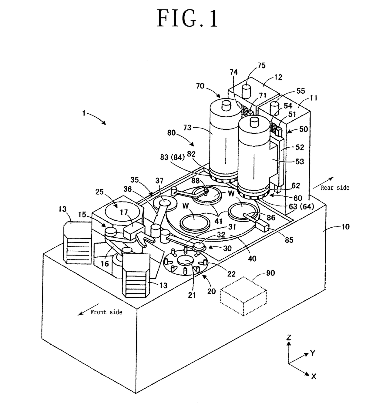
[0019]In the following, a grinding apparatus is described with reference to the accompanying drawings. FIG. 1 is a perspective view of a grinding apparatus according to an embodiment. It is to be noted that, in the present embodiment, the configuration of the grinding apparatus is not restricted to that depicted in FIG. 1. The grinding apparatus may be configured in any manner only if it can carry out a grinding work for a plate-shaped workpiece.

[0020]As depicted in FIG. 1, a grinding apparatus 1 is a processing apparatus of the full automatic type and is configured so as to fully automatically carry out a series of processes for a plate-shaped workpiece W including a carrying-in process, a rough grinding process, a finish grinding process, a washing process and a carrying-out process. The plate-shaped workpiece W is formed in a substantially disk shape and is configured from a semiconductor substrate, for example, of silicon, gallium arsenide or the like, an inorganic material subs...


PUM


Abstract

A grinding method includes a pre-grinding step of grinding a plate-shaped workpiece to a thickness just before a finish thickness is reached using a finish grinding unit, a thickness measuring step of measuring a thickness of the workpiece after the pre-grinding step, a calculation step of calculating, from the measured thickness of the workpiece, a variation amount of the distance between a holding face of the chuck table and a grinding face of a finish grindstone before and after inclination adjustment of the chuck table, and a height adjustment step of adjusting, on the basis of the variation amount, the inclination of the chuck table while adjusting the height of the finish grinding unit so that the relative moving speed between the finish grindstone and the workpiece in a state in which the grinding face contacts with an upper face of the workpiece becomes equal to zero.

Description

BACKGROUND OF THE INVENTION[0001]Field of the Invention[0002]The present invention relates to a grinding method for grinding a plate-shaped workpiece to a desired thickness while the thickness of the plate-shaped workpiece is measured.[0003]Description of the Related Art[0004]In a grinding process, a method is known wherein a plate-shaped workpiece is ground while the thickness thereof is measured by a height gauge of the contact type (for example, refer to Japanese Patent Laid-Open No. 2008-073785). In a height gauge of the contact type, a pair of contactors are contacted with an upper face of a plate-shaped workpiece and an upper face of a chuck table to detect the thickness of the plate-shaped workpiece from the difference in height between the contacting positions of the contactors. Further, as a grinding method of a bonded work configured from a plurality of plate-shaped workpieces, a method is known wherein the bonded work is ground while the thickness of the upper side work o...

Claims


Application Information

Patent Timeline
IPC IPC(8): B24B49/04H01L21/66H01L21/687H01L21/304B24B7/22B24B49/12
CPCB24B49/04B24B7/228H01L22/20H01L21/68785H01L21/304B24B49/12
Inventor YOSHIDA, SHINJI
Owner DISCO CORP
Learn More