
LED tube lamp

Active Publication Date: 2017-03-30
JIAXING SUPER LIGHTING ELECTRIC APPLIANCE
View PDF5 Cites 30 Cited by
  • Summary
  • Abstract
  • Description
  • Claims
  • Application Information

AI Technical Summary

Benefits of technology

The LED tube lamp has an opening that acts as a pressure-relieving tunnel to prevent electric shocks and to release air pressure when the temperature inside the lamp changes. The opening also allows for efficient heat dissipation, increasing the product's life span and reliability. The end cap can be easily assembled or disassembled from the tube because the gas can flow via the opening, and the pressure inside the tube and end cap remains constant. This ensures the efficiency of assembly and dissembling of the lamp and also prevents the risk of electric shock to the user.

Problems solved by technology

Besides, there is no opening on the tube for pressure releasing, then the reliability of the LED tube lamp is low.
Furthermore, there is a risk of electric shock to the user when the ruptured or broken LED tube lamp is uninstalled in the condition without electric shock prevention design.
Prior LED tube lamps have some issues.
When the LED tube lamp operates, the electronic components of the power supply inside the end cap continuously generate heat, and the generated heat cannot be dissipated by convection of air.
Instead, the heat accumulates inside the end cap, which negatively affects the products' life span and reliability.
Sudden change of the temperature may cause sudden increase or decrease of the pressure inside the end cap.
In addition, since continuous, high temperature of the end cap causes the increase of the pressure inside the end cap, the electronic components continuously suffering high temperature and high pressure are easily damaged.
High temperature and high pressure not only negatively affect the reliability of the LED tube lamp, but also raise the risk of spontaneous combustion of the electronic components, which may cause fire accident.
During an assembling process of the LED tube lamp, the end cap might have resistance to be assembled to the tube because the pressure inside the tube and the end cap increases along with the assembling process of the tube and the end cap, which negatively affect the efficiency of assembling.
When the LED tube lamp is being installed to or being uninstalled from a lamp base, there is a risk of electric shock to the user if the LED tube lamp is ruptured or broken or if the user accidently contacts exposed conductive pins at one end of the LED tube lamp while the other end is still electrically connected to the lamp base.
Therefore, user can easily aware that the structure of the tube is damaged and stop using it.
In addition, the bendable circuit sheet of the LED light strip is electrically connected to the power supply directly by the freely extending end portion formed at one end of the LED light strip rather than by traditional wire bonding, which remarkably lowers down the possibility of disconnection occurred between the LED light strip and the power supply during manufacturing, transportation, and usage of the LED tube lamp.

Method used


Image

  • LED tube lamp
  • LED tube lamp
  • LED tube lamp

Examples


Embodiment Construction

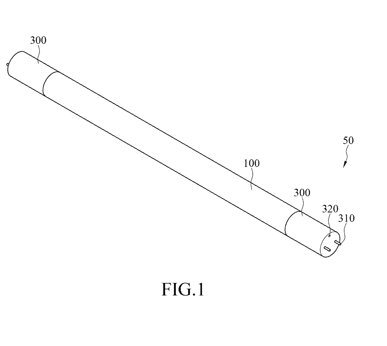
[0069]The instant disclosure provides an LED tube lamp to solve the abovementioned problems. The instant disclosure will now be described more fully hereinafter with reference to the accompanying drawings, in which exemplary embodiments of the disclosure are shown. This disclosure may, however, be embodied in many different forms and should not be construed as limited to the embodiments set forth herein. Rather, these embodiments are provided so that this disclosure will be thorough and complete, and will fully convey the scope of the disclosure to those skilled in the art. Like reference numerals refer to like elements throughout.

[0070]The terminology used herein is for the purpose of describing particular embodiments only and is not intended to be limiting of the disclosure. As used herein, the singular forms “a”, “an” and “the” are intended to include the plural forms as well, unless the context clearly indicates otherwise. It will be further understood that the terms “comprises”...


PUM


Abstract

An LED tube lamp includes a tube, two end caps, a power supply, and an LED light strip. The tube includes two rear end regions, two transition regions, and a main body region. The end caps are respectively connected to the rear end regions. The power supply is in one or both of the end caps. The LED light strip including one or more LED light sources is in the tube. The LED light sources are electrically connected to the power supply via the LED light strip. The end cap includes a lateral wall, an end wall, and at least one opening for heat dissipation and / or pressure releasing. The at least one opening penetrates through the end cap with a light sensor inside the end cap collimating with the opening.

Description

CROSS-REFERENCE TO RELATED APPLICATIONS[0001]This application is a continuation-in-part application claiming benefits of U.S. application Ser. No. 15 / 087,088 filed on 2016 Mar. 31, and U.S. application Ser. No. 14 / 865,387 filed on 2015 Sep. 25, and claiming priority of Chinese Patent Application no. CN201610327806.0 filed on 2016 May 18, Chinese Patent Application no. CN201610044148.4 filed on 2016 Jan. 22, and Chinese Patent Application no. CN201510848766.X filed on 2015 Nov. 27, the disclosures of which are incorporated herein in their entirety by reference.TECHNICAL FIELD[0002]The instant disclosure relates to illumination devices, and, more particularly, to an LED tube lamp and components thereof comprising the LED light sources, a tube, electronic components, and end caps.RELATED ART[0003]LED lighting technology is rapidly developing to replace traditional incandescent and fluorescent lightings. LED tube lamps are mercury-free in comparison with fluorescent tube lamps that need...

Claims


Application Information

Patent Timeline
IPC IPC(8): F21K9/278F21V29/508F21V15/015F21V29/89F21K9/272F21S4/24H05B44/00
CPCF21K9/278F21K9/272F21S4/24F21Y2103/10F21V29/89F21V29/508F21Y2115/10F21V15/015F21V3/02F21V17/101F21V23/02H05K1/118H05K1/189H05K2201/10106F21V29/83F21K9/66H05K3/363H05B45/00H05B47/11Y02B20/40F21K9/27
Inventor JIANG, TAO
Owner JIAXING SUPER LIGHTING ELECTRIC APPLIANCE
Learn More