Device for reducing effective radar cross section

a technology for effective radar and cross section, which is applied in special-purpose vessels, offensive equipment, transportation and packaging, etc., can solve the problems of making radar detection more difficult, and reducing so as to reduce the effective radar cross section (rcs) of naval vessels, low space requirement, and low weight

Inactive Publication Date: 2017-03-30
THYSSENKRUPP MARINE SYST GMBH +1
View PDF2 Cites 1 Cited by
  • Summary
  • Abstract
  • Description
  • Claims
  • Application Information

AI Technical Summary

Benefits of technology

The present invention provides a device for reducing the radar cross section of a naval vessel that has a low space requirement and is inexpensive. The device includes a cladding panel that is permeable to radar beams and a reflection means that is embedded in the cladding panel and aligned at least partially inclined with respect to the main plane of the cladding panel. The reflection means reflects radar beams in a way that reduces the incident radar beams from being reflected directly back to the sender of the radar waves, while retaining a neutral or conventional outer appearance of the naval vessel. The device can be retrofitted easily and flexibly and can even be used as camouflage for cargo. It is advantageously possible to dispense with the cost-intensive transformation of the vessel or cargo geometry.

Problems solved by technology

It is endeavoured to reduce the effective radar cross section (RCS) of naval vessels, in particular when they are for military use, to make detection of the naval vessel more difficult.
Radar detection is thus made more difficult by fewer radar echoes being reflected in the direction of the detecting radar set.
However, these design objectives cannot always be met.
For example, cargo is often transported on modern naval vessels in standardized ISO containers that are securely lashed on deck and, in compliance with their standard, are always cuboidally formed, so that it is not practical to do away with all right angles and create spherical surfaces.
Such cladding elements are comparatively cost-intensive and complex.
A disadvantage of this solution is that a smooth surface cannot be achieved and there is a considerable space requirement.

Method used


Image

  • Device for reducing effective radar cross section

Examples


Embodiment Construction

[0017]In the various figures, the same parts are always provided with the same designations, and are therefore in each case also generally only referred to or mentioned once.

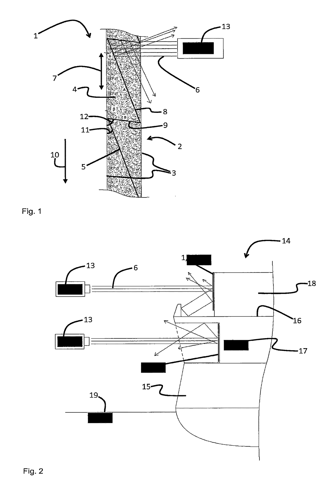
[0018]In FIG. 1, a schematic view of a sectional image of a device 1 for reducing the effective radar cross section (RCS) of a naval vessel 14 according to an exemplary embodiment of the present disclosure is represented.

[0019]The device 1 comprises a cladding panel 2, which takes the form of a rigid or semirigid sandwich panel. For this, the cladding panel 2 comprises two outer layers 3 of glass-fibre reinforced plastic (GRP) and a core 4, which is arranged between the two outer layers 3. The core 4 comprises a foam core, preferably a polyurethane foam (PU). The composite of the outer layers 3 with the foam core provides the cladding panel 2 with a high load-bearing capacity and great stiffness, with at the same time very low weight. Moreover, the cladding panel 2 is permeable to radar beams 6, so that no appre...


PUM


Abstract

A device for reducing the effective radar cross section (RCS) of a naval vessel is proposed, the device comprising a cladding panel, which can be mounted on vessel superstructures or cargo of the naval vessel, the cladding panel being permeable to radar beams, the device also comprising a reflection means, which reflects radar beams, and the reflection means also being embedded in the cladding panel and being aligned at least partially inclined with respect to a main plane of extent of the cladding panel.

Description

PRIOR ART[0001]The present disclosure is based on a device for reducing the effective radar cross section of a naval vessel which comprises a reflection means for the reflection of radar beams.[0002]It is endeavoured to reduce the effective radar cross section (RCS) of naval vessels, in particular when they are for military use, to make detection of the naval vessel more difficult. Radar detection is based on the principle according to which radar waves are emitted by a radar set as primary waves and are reflected by the object to be detected and returned as secondary waves in the form of radar echoes. The secondary waves are detected by the radar set and used to obtain information concerning the distance of the object, the direction of the object and possibly the size and contour of the object. Radar detection is thus made more difficult by fewer radar echoes being reflected in the direction of the detecting radar set. The effective radar cross section (RCS) or radar signature is s...

Claims


Application Information

Patent Timeline
IPC IPC(8): B63G13/02H01Q15/18H01Q1/34
CPCB63G13/02B63G2013/027H01Q15/18H01Q1/34F41H3/00B63G8/34
Inventor EWERS, DIRKDETERMANN, WOLFRAM
Owner THYSSENKRUPP MARINE SYST GMBH
Why Eureka
Try Eureka