System, including a bending bar and a bending cage, for bending a plate in a plane of the plate

Active Publication Date: 2017-03-30
TRIMED
View PDF4 Cites 3 Cited by
  • Summary
  • Abstract
  • Description
  • Claims
  • Application Information

AI Technical Summary

Benefits of technology

The patent describes a bending cage for a plate or rod that allows bending forces to be applied to the plate or rod through the bending cage. The bending cage has elongate openings in its front and rear surfaces, with the openings having upper and lower parallel edges. The bending cage is designed to restrict rotational movement of the bending bar about an axis parallel to the primary axes of the openings. The bending cage allows free movement of the bending bar in a direction parallel to the primary axis of the openings, while preventing rotational movement about other axes. This design allows for precise bending forces to be applied to the plate or rod through the bending cage.

Problems solved by technology

Unfortunately, plates sometime require the addition of a horizontal bend, around an axis that is perpendicular to the plane of the plate.
In this direction of bending, bending irons typically do not work well, if at all.
This causes the bending tools to stabilize in a position that is not opposite and coplanar, resulting in misdirection of the applied bending force in a direction that is outside the plane of the plate.
In addition, the torsional play of the plate within the opening of the bending tool results in a tendency for the end of the plate to slip out of the bending tool.
Since this direction of bending is typically the most difficult, being through the width of the plate rather than the thickness, any torsional movement of the plate (1) reduces the effectiveness of maintaining all of the applied load along the desired axis of the bend, and (2) directs a bending axis that is oblique to any principle axis of the plate resulting in significant increase in the amount of applied load required to create a plate bend.
Often, this may exceed the ability of a user to generate the required force.
Other bending instruments have been used, but require much heavier, bulkier, and more costly types of instruments.
These instruments still have the problematic issue of controlling a bending force to be efficiently and effectively transferred to the plate in a horizontal direction (around the axis that is perpendicular to the plane of the plate).
In addition, these instruments do not address the tendency for the plate to twist or slip out of the holding bracket while this type of force is applied.

Method used


Image

  • System, including a bending bar and a bending cage, for bending a plate in a plane of the plate
  • System, including a bending bar and a bending cage, for bending a plate in a plane of the plate
  • System, including a bending bar and a bending cage, for bending a plate in a plane of the plate

Examples


Embodiment Construction

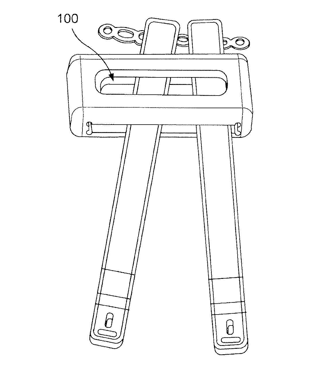
[0048]As shown in FIG. 10, in a preferred embodiment, the bending cage (1) has a front opening (20) and a rear opening (21), each dimensioned to allow passage of a bending bar or bending iron (30, 31).

[0049]FIG. 11 shows the front opening (20) of the bending cage (1) having two parallel edges separated by a vertical distance (3) and having a horizontal length (2). The vertical distance (3) allows a snug fit for a vertical dimension (e.g., thickness) of a bending bar or bending iron (30, 31) while the horizontal length (2) permits free horizontal motion for the bending bar or being iron (30, 31) within the front opening (20). Thus, a range along horizontal length (2) is provided for moving at least one bending iron (30, 31) in a horizontal direction while vertical distance (3) prevents spinning or rotational movement of the bending bar or bending iron (30, 31) and maintains an applied force constrained along an axis directed by the horizontal length (2) in the bending cage (1).

[0050]...


PUM

PropertyMeasurementUnit
Lengthaaaaaaaaaa
Lengthaaaaaaaaaa
Thicknessaaaaaaaaaa

Abstract

A system and method for bending a bone fixation plate in the horizontal plane of the plate. The apparatus and method provide for optimization of applied bending moments by controlling the orientation of a bending tool to prevent deviation from an axis of bending. The system includes a bending bar or bars with an aperture or slot for engaging a plate or rod and a bending cage that can be in the shape of a rectangular box having a front surface separated from a rear surface by a distance. The front surface has a front elongate opening and the rear surface has a rear elongate opening. The front and rear openings are each formed by two parallel edges separated by a vertical distance and having a horizontal length. The relative dimensions of the respective bending bars and openings are such that the bending cage can be used to permit free movement of the bending bars in a direction parallel to the primary axis of the elongate openings but to prevent rotational movement of the bending bars about an axis substantially parallel to the length of the bending bars.

Description

CROSS REFERENCE APPLICATION[0001]This application claims the benefit of U.S. Provisional Application Ser. No. 62 / 234,236 filed Sep. 29, 2015, the content of which is incorporated herein by reference.FIELD OF THE INVENTION[0002]The present invention relates to an instrument for bending a bone fixation plate in the horizontal plane of the plate. More particularly, the instrument provides for optimization of applied bending moments by controlling the orientation of a bending tool to prevent deviation from an axis of bending.BACKGROUND OF THE INVENTION[0003]Plate and screw fixation of bones is a generally accepted method of treatment for several types of conditions that affect structural integrity of skeletal elements. A majority of plates are made from a malleable material such as a metal or metal alloy. One advantage of these types of materials is that they allow modification of the shape of the plate for more intimate contact with a bone surface which often may have a complex surface...

Claims


Application Information

Patent Timeline
IPC IPC(8): B21D7/02B21D11/20B21D5/00
CPCB21D7/02B21D11/20B21D5/00A61B17/8863
Inventor TELLMAN, LUKASSOVEREIGN, RANDALL JAMES
Owner TRIMED
Why Eureka
Try Eureka