Time-space methods and systems for the reduction of video noise

Inactive Publication Date: 2017-03-23
WRNCH INC
View PDF2 Cites 38 Cited by
  • Summary
  • Abstract
  • Description
  • Claims
  • Application Information

AI Technical Summary

Benefits of technology

The patent text describes a method and system for reducing video noise and motion blur in video systems. The technical effects of the invention include improved accuracy in motion estimation and video denoising, as well as reduced noise levels in video frames. The invention also addresses the issue of over- or under-estimating noise levels in video and takes into account the impact of noise on motion vectors and color video denoising. The invention uses a time-space video filter to accurately analyze and reduce video noise and motion blur. The method and system can be used in video capture devices, video coding, stabilization, enhancement, and deblurring applications. The invention also includes a motion vectors bank for accurate motion estimation and a comparison of the proposed method with other denoising techniques.

Problems solved by technology

Recent advances in denoising have achieved remarkable results [Reference 1]-[Reference 9], however, the simplicity of their noise source modeling makes them impractical for real-world video noise.
However, in practice noise can be over or underestimated, signal-dependent (Poissonian-Gaussian), or frequency-dependent (processed).
The assumption that the noise is uniformly distributed over the whole frame, causes motion and smoothing blur in the regions where motion vectors and noise level differs from reality, since noise and image structure are mistaken.
Additional issues of recent video denoising methods is that they are computationally expensive such as [Reference 2], [Reference 4], and very few handle color video denoising.
Accordingly, the above issues affect the way in which the noise is estimated in video and the way in which motion is estimated.

Method used


Image

  • Time-space methods and systems for the reduction of video noise
  • Time-space methods and systems for the reduction of video noise
  • Time-space methods and systems for the reduction of video noise

Examples


Embodiment Construction

[0027]It will be appreciated that for simplicity and clarity of illustration, in some cases, reference numerals may be repeated among the figures to indicate corresponding or analogous elements. In addition, some details or features are set forth to provide a thorough understanding of the embodiments described herein. However, it will be understood by those of ordinary skill in the art that the embodiments described herein are illustrative examples that may be practiced without these details or features. In other instances, well-known methods, procedures and components have not been described in detail so as not to obscure the invention illustrated in the examples described herein. Also, the description is not to be considered as limiting the scope of the example embodiments described herein or illustrated in the drawings.

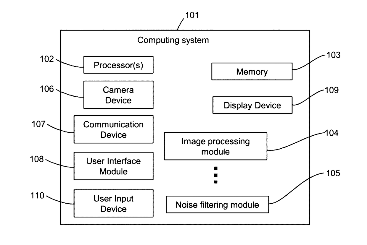
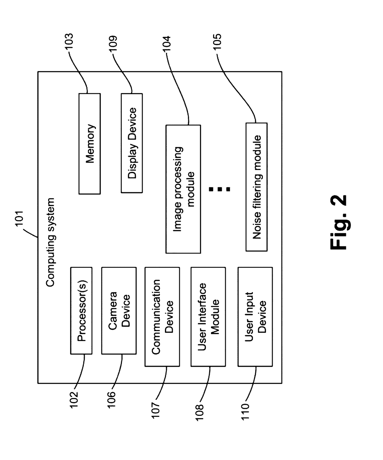
[0028]It is herein recognized that it is desirable to have a multi-level video denoising method and system that automatically handles three types of noise: additiv...


PUM


Abstract

A time-space domain video denoising method is provided which reduces video noise of different types. Noise is assumed to be real-world camera noise such as white Gaussian noise (signal-independent), mixed Poissonian-Gaussian (signal-dependent) noise, or processed (non-white) signal-dependent noise. This method comprises the following processing steps: 1) time-domain filtering on current frame using motion-compensated previous and subsequent frames; 2) restoration of possibly blurred contents due to faulty motion compensation and noise estimation; 3) spatial filtering to remove residual noise left from temporal filtering. To reduce the blocking effect, a method is applied to detect and remove blocking in the motion compensated frames. To perform time-domain filtering weighted motion-compensated frame averaging is used. To decrease the chance of blurring, two levels of reliability are used to accurately estimate the weights.

Description

RELATED APPLICATIONS[0001]This application claims priority to U.S. Patent Application No. 61 / 993,884, filed May 15, 2014, titled “Time-Space Method and System for the Reduction of Video Noise”, the entire contents of which are hereby incorporated by reference.TECHNICAL FIELD[0002]The following invention or inventions generally relate to image and video noise analysis and specifically to the reduction of video noise.DESCRIPTION OF THE RELATED ART[0003]Modern video capturing devices often introduce random noise and video denoising is still an important feature for video systems. Many video denoising approaches are known to restore videos that have been degraded by random noise. Recent advances in denoising have achieved remarkable results [Reference 1]-[Reference 9], however, the simplicity of their noise source modeling makes them impractical for real-world video noise. Mostly, noise is assumed a) to be zero-mean additive white Gaussian and b) accurately pre-estimated. However, in pr...

Claims


Application Information

Patent Timeline
IPC IPC(8): G06T5/00G06T5/20G06T5/50
CPCG06T5/002G06T5/50G06T2207/20182G06T2207/10016G06T5/20H04N5/21H04N19/117H04N19/172H04N19/154H04N19/177H04N19/80G06T5/70
Inventor RAKHSHANFAR, MEISAMAMER, MARIA AISHY
Owner WRNCH INC
Why Eureka
Try Eureka