
Bilateral Frontal Sinus Device

a frontal sinus and device technology, applied in the field of bilateral frontal sinus devices, can solve the problems of rarely considering stenting, no good commercially available option for short or long-term stenting of the entire frontal sinus cavity, and difficult frontal sinus surgery

Inactive Publication Date: 2017-03-23
ROTENBERG BRIAN WILLIAM
View PDF8 Cites 0 Cited by
  • Summary
  • Abstract
  • Description
  • Claims
  • Application Information

AI Technical Summary

Benefits of technology

This patent describes a device for delivering substances to the frontal sinus cavity. The device includes an elongated horizontal tube, an elongated vertical tube, and an interstitial member therebetween. The interstitial member is flexible for movement between 1-10 degrees through to 180 degrees. The device can receive, hold, or disperse a substance, and can be used with a syringe attachment or a retractable tubular insert for manual draining of fluids. The device is made of silicon rubber tubing and a retractable tubular insert made of a harder material. Overall, the device provides an effective tool for delivering substances to the frontal sinus cavity.

Problems solved by technology

Frontal sinus surgery is one of the most challenging areas of sinus surgery due to the difficult visualization and complex anatomy of patients.
However, rarely is stenting considered due to the lack of adequate commercially available products.
There are currently no good commercially available options for short or long term stenting of the entire frontal sinus cavity following sinus surgery.
However, the Rains bulbous stent is very inflexible and due to the relatively inflexible structure of the stent, it causes trauma to the delicate area that is to be stented, and results in a lower patency rate.
Additionally, due to the very complex anatomy of the frontal sinus cavity, the Rains stent is also relatively large and difficult to place.
Accordingly, the field of frontal sinus surgery suffers from a lack of a frontal sinus stent that may be releasably secured in all areas of the frontal sinus drainage pathway.

Method used


Image

  • Bilateral Frontal Sinus Device
  • Bilateral Frontal Sinus Device
  • Bilateral Frontal Sinus Device

Examples


Embodiment Construction

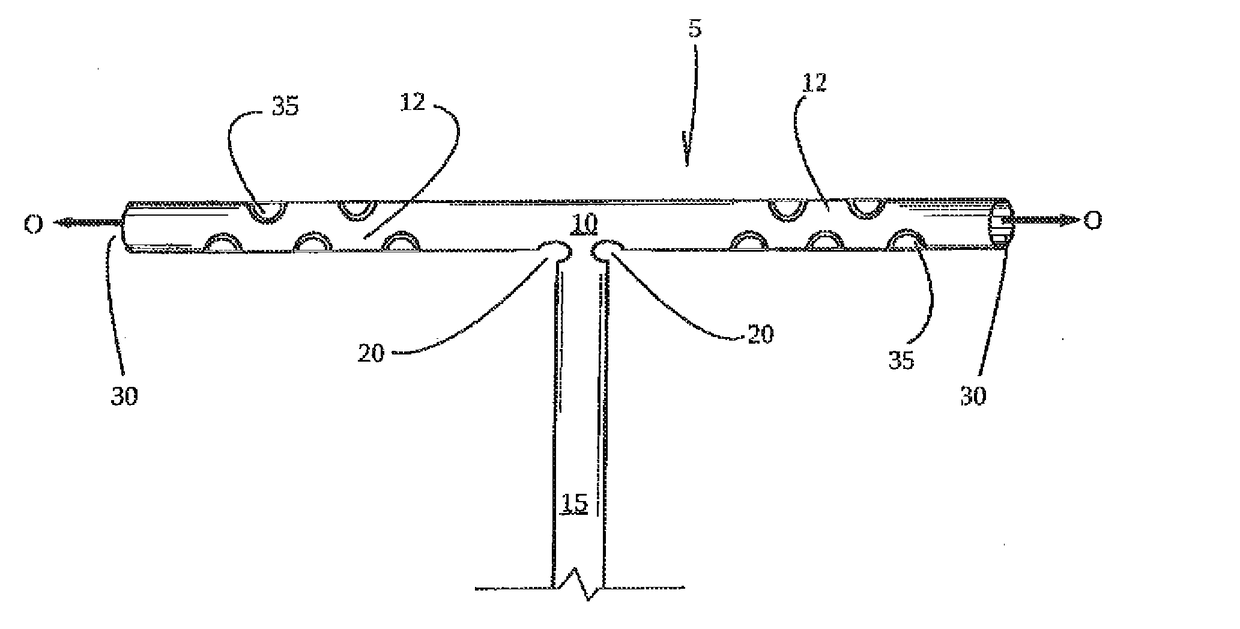
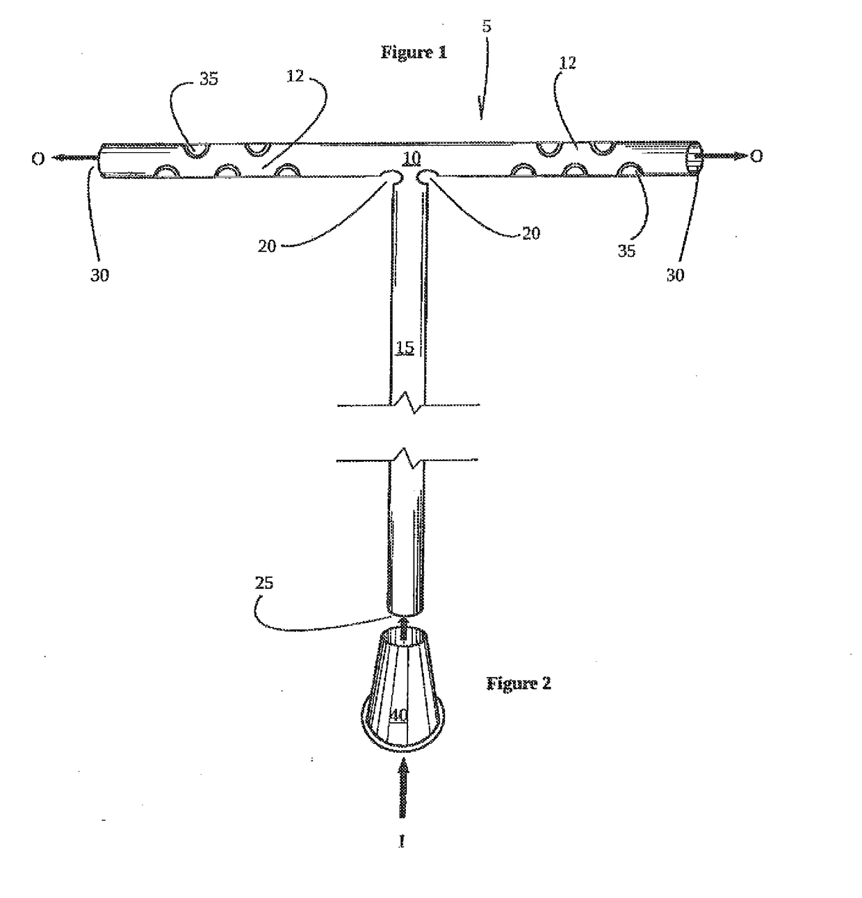
[0017]Referring to FIG. 1, a bilateral frontal sinus device 5 is shown in an open position providing a tubular structure of a predetermined length of horizontal tube 10 defined as arms 12 adjoined a predetermined length of vertical tube 15. The horizontal and vertical tubes 10, 15 are adjoined at a point along the length of each tube defined by a position of an interstitial member 20 therebetween. The term “adjoined” will be construed to include integral formations as well as connections of separate parts.

[0018]The vertical tube 15 receives at least one substance from source I through opening or aperture 25 and out O via the arms 12 of horizontal tube 10, through at least one primary aperture 30, secondary aperture 35 or a combination of both depending on the chosen area of the bilateral sinus to target. The tubular structure of the bilateral frontal sinus device 5 when in an open position resembles a T-shaped structure, however, to fit a specific anatomy of a patient this shape can...


PUM


Abstract

A bilateral frontal sinus insert which has a flexible body defining an interstitial member adjacent a horizontal tube and a vertical tube. The flexible body having entry and exits apertures for fluids and or particulates in fluid form. The fluids or particulates can include medicines. The body flexes for insertion within the sinus area, positioning within the sinus area and for extraction from the sinus area. The interstitial member is defined by an aperture or by a layer of flexible material in between the vertical and horizontal tubes. Downward or upward movement of the vertical tube is used to reduce or increase the width between the interstitial members for retaining or releasing fluid in a controlled manner.

Description

[0001]This is a non-provisional utility patent application which claims priority to copending provisional application Ser. No. 62 / 222,247 filed Sep. 23, 2015, which is incorporated herein for all purposes.TECHNICAL FIELD[0002]The technical field of the invention relates to a bilateral frontal sinus device, system and use thereof for controlled use of medications and / or maintaining fluid flow during and after irrigation of the entire frontal sinus cavity and releasably retaining the device in the functional position.BACKGROUND OF THE INVENTION[0003]Frontal sinus surgery is one of the most challenging areas of sinus surgery due to the difficult visualization and complex anatomy of patients. The ultimate success or failure of endonasal frontal sinus surgical procedures is determined essentially by the rate of restenosis of the frontal sinus outflow tract. It is known that long-term stenting for a period of several months reduces the rate of restenosis. However, rarely is stenting consi...

Claims


Application Information

Patent Timeline
Patent Type & Authority Applications(United States)
IPC IPC(8): A61M25/00A61M3/02
CPCA61M25/0041A61M25/0097A61M2210/0681A61M3/0279A61M25/01A61M25/0043A61M25/0071A61M25/0074A61M25/007A61M27/00A61M31/00A61M39/10
Inventor ROTENBERG, BRIAN WILLIAM
Owner ROTENBERG BRIAN WILLIAM
Learn More